


Manual Operation
R&S
®
SMBV100A
101
Operating Manual 1176.8016.02 ─ 17
Example:
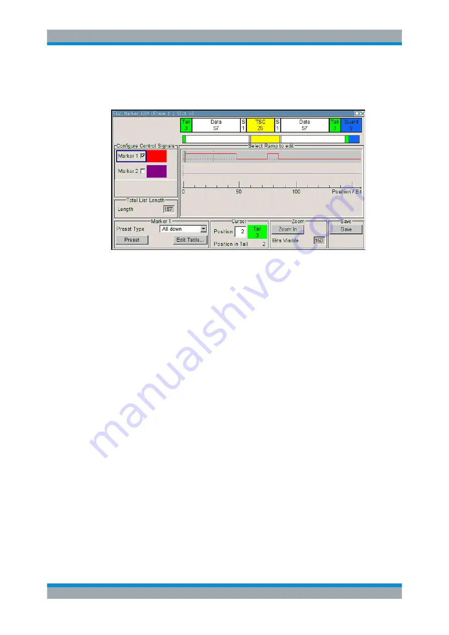
The following figure shows the "Slot Marker Definition Editor" of the "GSM/EDGE" dia-
log as an example.
The upper area displays the signal for which the marker signals are to be defined. On
the left side, the available signals (marker and control signals) are listed and colour-
coded.
Auxiliary functions are offered in the lower editor area, e.g. presetting for the ramps in
the marker signal, cursor positioning by entering the bit position and possible editing by
means of value entries in a table.
The actual graphic definition of the control signals occurs in the center area of the edi-
tor. Each control signal is represented by means of a colored line along the bit axis. A
cursor can be shifted alongside this line and marks the position where a ramp is to be
set. The color of the cursor changes depending on the current function.
Use the ENTER key to switch over between the colors (and therefore functions):
●
black: marks the bit position on the marker line
●
yellow: sets a ramp
●
green: activates the marked ramp for shifting.
Accessing control and marker list
1. To access the control list editor (e.g. "CList Dig Mod") and open an existing list for
editing, use the arrow keys to select "Custom Digital Mod > List Management >
Edit Control List".
2. To access the slot marker list editor (e.g. "Slot Marker") and open an existing list
for editing, use the arrow keys to select "GSM/EDGE > Burst Editor > Slot Marker
Definition".
Editing an existing control or marker list
1. Activate control/marker signal line for editing.
Use the arrow keys to mark the editable graphic area and press the ENTER key.
Editors


