IO-390-D Series Engine Maintenance Manual
72-30
© 2020 Avco Corporation. All Rights Reserved
Page 226
March 2020
IO-390-D Series Engine Maintenance Manual
W.
Lubricate rocker contact surfaces with Modoc
®
Oil 175.
NOTICE:
If a cork rocker box cover gasket is installed, torque the rocker box cover screws to
50 in.-lb. (5.6 Nm). Do not reuse cork gaskets.
X.
Examine the silicone rocker box cover gasket to make sure it is intact and not deformed or
damaged. Replace as necessary.
Y.
Install the silicone rocker box cover gasket and rocker box cover with screws on each rocker
box. Torque the screws to 35 in.-lb. (4.0 Nm).
Z.
Remove the vented plug from each spark plug hole.
AA.
Install the top and bottom spark plugs as per the section “Spark Plug Installation” in Chapter
74-20.
AB. Remove the caps from the fuel line and fuel injection nozzle and reconnect the fuel line to
the injection nozzle. Refer to the latest revision of the Service Table of Limits - SSP-1776
for torque values.
AC. Install the clamps that attach the fuel line to the shroud tube per instructions in the latest
revision of Service Bulletin No. SB-342.
AD. Install the applicable intake pipe on the cylinder per the “Intake Pipe Installation” procedure
in Chapter 72-80. Install the applicable exhaust pipe on the cylinder per the airframe
manufacturer’s instructions.
AE. Intercylinder Baffle Installation
(1)
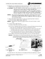
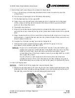
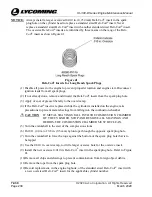
Engage the "S-Type" retaining hook (Figure 3) through the hole in the baffle.
(2)
Put the baffle in position beneath and between the cylinders and turn the hook up between
the cylinder barrels.
(3)
Put a baffle retainer in place between the cylinders and bring the retainer hook through
the slot in the retainer. The retainer is forced down until the hook is above the surface of
the retainer far enough to be engaged over the bridge between the slots in the retainer.
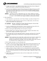
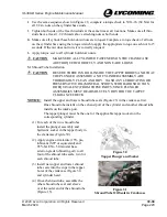
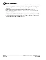
AF. Oil Drain Tube Installation
(1)
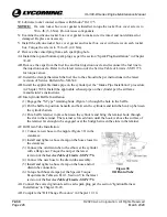
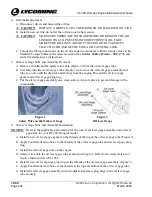
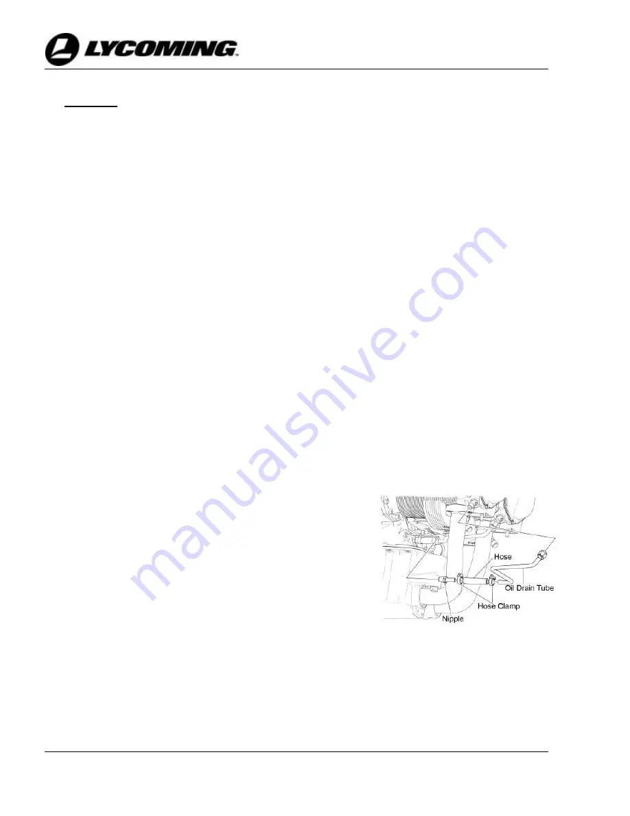
Connect a new hose to the nipple (Figure 38) in the
crankcase.
(2)
Install and tighten a hose clamp on the hose closest to
the crankcase.
(3)
Connect the oil drain tube to the elbow at the cylinder
with a flange nut. Torque the nut per the latest
revision of the
Service Table of Limits - SSP-1776.
(4)
Connect the new hose to the drain tube assembly.
(5)
Install and tighten a hose clamp on the hose and oil
drain tube connection.
(6)
Torque both hose clamps per the Special Torque
Requirements Tables in Part 1, Section V in the latest
revision of the
Service Table of Limits - SSP-1776
.
Figure 38
Oil Drain Tube
AG. Connect the correct ignition lead to each spark plug per the section “Ignition Harness
Installation” in Chapter 74-20.
AH. Complete the “Oil Change Procedure” in Chapter 12-10.


