IO-390-D Series Engine Maintenance Manual
72-20
© 2020 Avco Corporation. All Rights Reserved
Page 166
March 2020
IO-390-D Series Engine Maintenance Manual
(b)
Make sure the gage is on the bottom of the groove.
(c)
Pass the gage through the ends of the circlip.
(d)
Move the gage back and forth.
(e)
The gage must pass the ends of the circlip.
(f)
When moved back and forth, the gage must be clear of the inside edge of the top of
the circlip.
(10)
If the gage does not move freely between the ends and under the top of the circlip, the
circlip seating is not correct. Install the circlip again and complete a check of the circlip
seating again per the previous steps. The circlip must be seated correctly.
15.
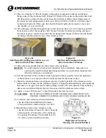
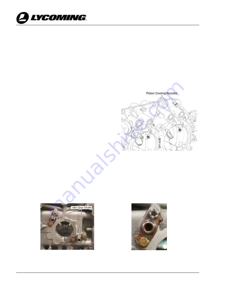
Piston Cooling Nozzle Installation (if removed)
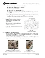
Figure 58
Piston Cooling Nozzles
A.
Apply a coating of engine oil to all of the
cleaned and inspected/acceptable piston
cooling nozzles.
B.
Install two piston cooling nozzles in each
crankcase half (Figure 58).
C.
Torque each piston cooling nozzle to 100 in.-
lb. (11 Nm).
16.
Crankshaft Idler Gear Shaft Installation
A.
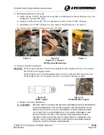
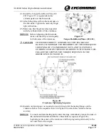
Install the crankshaft idler gear shaft (for the left idler gear) in the crankcase with a nut and
bolt (Figure 59). Torque the bolt to 17 ft.-lb. (23 Nm). Torque the nut to 12 ft.-lb. (16 Nm).
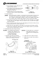
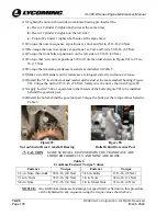
Safety wire the nut and bolt as shown in Figure 60.
B.
Install the crankshaft idler gear shaft (for the right idler gear) in the crankcase with two bolts
(Figure 59). Torque the bolts to 17 ft.-lb. (23 Nm). Safety wire the bolts as shown in Figure
60.
Figure 59
Shaft Installation in the Crankcase
for Left and Right Crankshaft Idler Gears
Figure 60
Safety Wire on the
Crankshaft Idler Gear Shaft

