IO-390-D Series Engine Maintenance Manual
© 2020 Avco Corporation. All Rights Reserved
72-10
March 2020
Page 117
IO-390-D Series Engine Maintenance Manual
Table 2 (Cont.)
Sequence of Engine Assembly Procedures
Step
Reference
Step
Reference
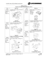
Step 7
“Crankshaft Idler Gear Shaft
Installation” procedure in Chapter 72-
20
Step 10
“Tappet Assembly Installation”
procedure in Chapter 72-20
Install the
crankshaft
idler gear
shafts
(Figure 6).
Install the
tappet
assemblies
(Figure 9).
Figure 6
Crankshaft Idler Gear Shafts
Figure 9
Tappets and Oil Seal Rings
Step 8
Install the
oil plugs (if
removed)
(Figure 7).
“Oil Plug Installation” procedure in
Chapter 72-20
Step 11
Install the
main
bearings,
bolts, and
O-rings in
the
crankcase
(Figure 10).
“Crankshaft Bearing and O-Ring
Installation” procedure in Chapter 72-
20
Figure 7
Oil Plugs
Figure 10
Main Bearings and O-Rings
Step 9
“Oil Pressure Relief Valve Installation”
procedure in Chapter 72-50
Step 12
“Propeller Governor Drive Installation”
in Chapter 72-20
Install the
oil pressure
relief valve
(Figure 8).
Install the
propeller
governor
drive
(Figure 11).
Figure 8
Oil Pressure Relief Valve
Figure 11
Propeller Governor Drive

