IO-390-D Series Engine Maintenance Manual
72-70
© 2020 Avco Corporation. All Rights Reserved
Page 246
March 2020
IO-390-D Series Engine Maintenance Manual
4.
Alternator and Bracket Removal
CAUTION
DISCONNECT THE BATTERY AND ENSURE EIS/MAGNETOS ARE
PROPERLY GROUNDED TO PREVENT ELECTRICAL SHOCK AND
ACCIDENTAL ENGINE START.
A.
To remove the alternator:
(1)
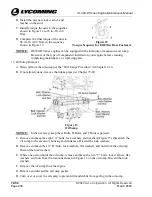
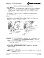
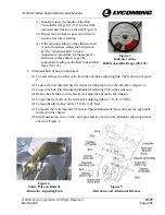
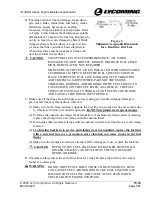
Cut and remove the safety wire/cable from the two bolts on the alternator adjusting link
where shown in Figure 4.
(2)
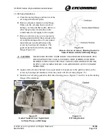
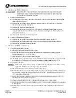
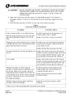
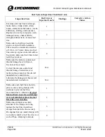
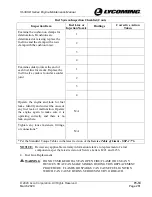
Remove the two bolts and two different washers (STD-1727 and STD-35) from the
alternator adjusting link (Figure 5).
(3)
Remove the alternator adjusting link.
(4)
Remove the two cotter pins (STD-713), two bolts, two slotted nuts, shims and three
washers from the alternator bracket, strut, and alternator (Figure 5). Discard the cotter
pins and slotted nuts.
(5)
Remove the alternator and alternator belt.
B.
To remove the alternator bracket:
(1)
Remove the two bolts and lockplate from the alternator bracket (Figure 5).
(2)
Remove the two bolts and washer (STD-690) from the strut and alternator bracket.
(3)
Remove the strut and alternator bracket.
5.
Alternator and Bracket Installation
A.
To install the alternator bracket:
(1)
Mount the alternator bracket on the engine.
(2)
Install the lockplate with two bolts and washers on the alternator bracket (Figure 5).
Torque the bolts to 17 ft.-lb. (23 Nm).
(3)
Bend the tabs of the lockplate against the bolts.
(4)
Attach the strut to the alternator bracket with the two bolts and washers. Torque the bolts
in accordance with the latest revision of the
Service Table of Limits SSP - 1776
.
B.
To install the alternator:
NOTICE:
Refer to the latest revision of Service Instruction No. SI-1154 to ensure the correct
approved alternator for your engine is to be installed.
(1)
Mount the alternator on the alternator bracket (Figure 5).
(2)
Install the bolt, two new slotted nuts, shims (as many as necessary) and three washers on
the alternator bracket and alternator as shown in Figure 5. Install a new cotter pin (STD-
713) in each new slotted nut.
(3)
Install the alternator adjusting link with the two bolts and different washers (STD-1727
and STD-35) where shown in Figure 5.
(4)
Examine the alternator belt per “Alternator Belt Inspection” in this chapter.
(5)
Install the alternator belt on the alternator per the “Alternator Belt Installation” procedure
in this chapter.
(6)
Install safety wire/cable on the cotter pin and the alternator adjusting link as shown in
Figure 4.

