IO-390-D Series Engine Maintenance Manual
© 2020 Avco Corporation. All Rights Reserved
72-20
March 2020
Page 153
IO-390-D Series Engine Maintenance Manual
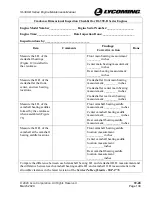
Connecting Rod Inspection Checklist for IO-390-D Series Engines (Cont.)
Item
Comments
Findings/Corrective Action
Done
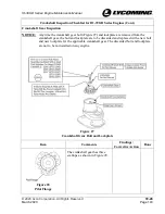
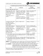
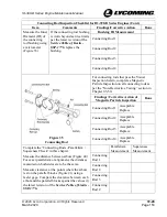
Measure the Inner
Diameter (ID) of
the connecting
rod bushing using
a micrometer
(Figure 35)
If the connecting rod bushing
is worn beyond service limits
per the latest revision of the
Service Table of Limits -
SSP-1776
, replace the
bushing.
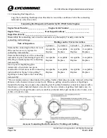
Bushing ID Measurement
Connecting Rod 1
Connecting Rod 2
Connecting Rod 3
Connecting Rod 4
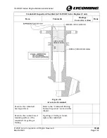
Figure 35
Connecting Rod
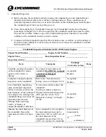
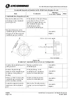
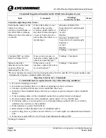
For connecting rods that pass the Visual
Inspection herein, complete a Magnetic
Particle Inspection on all connecting rods as
per the “Non-Destructive Testing” section in
Chapter 05-50.
Findings/ Corrective Action of
Magnetic Particle Inspection
Done
Connecting Rod 1
Acceptable
Replace
Connecting Rod 2
Acceptable
Replace
Connecting Rod 3
Acceptable
Replace
Connecting Rod 4
Acceptable
Replace
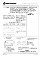
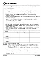
Complete the “Connecting Rods - Parallelism /
Squareness Check” in this chapter.
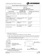
Measure the distance between arbors (Figure 40).
For exact parallelism or alignment, the distances
measured on both sides are to be the same.
Measure clearance at the points where the arbors
rest on the parallel blocks (Figure 41) using a
feeler gage. Compare the clearance between each
arbor and the parallel blocks against the values in
the latest revision of the
Service Table of Limits -
SSP-1776.
Parallelism
Measurement
Squareness
Measurement
Connecting
Rod 1
Connecting
Rod 2
Connecting
Rod 3
Connecting
Rod 4

