IO-390-D Series Engine Maintenance Manual
© 2020 Avco Corporation. All Rights Reserved
72-20
March 2020
Page 175
IO-390-D Series Engine Maintenance Manual
A.
Assemble the Crankcase Halves
CAUTION
THE CRANKCASE HALVES ARE A MATCHED SET, IF ONE HALF IS
CRACKED OR DAMAGED BOTH HALVES MUST BE REPLACED.
ONLY LYCOMING-APPROVED SEALANTS ARE TO BE USED
DURING CRANKCASE ASSEMBLY. USE OF ANY OTHER NON-
APPROVED SEALANT COULD RESULT IN A LOSS OF CLAMPING
FORCE AND/OR TORQUE.
IN THE NEXT STEP, DO NOT GET THE GASKET COMPOUND IN THE
BORE OF THE NOSE SEAL OR IN ANY CRANKCASE BORE. IF ANY
NON-HARDENING GASKET COMPOUND GETS INTO THE NOSE
SEAL BORE OR ANY CRANKCASE BORE, CAREFULLY REMOVE
THE GASKET COMPOUND WITH A SOFT CLOTH AND SOLVENT
(ACETONE, MEK, OR EQUIVALENT). DO NOT GET MEK ON THE
CRANKSHAFT OIL SEAL.
(1)
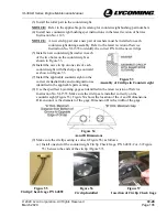
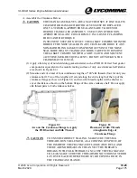
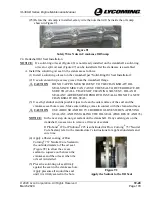
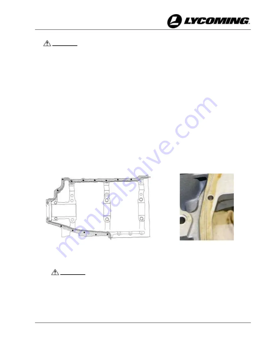
Apply a thin layer of non-hardening gasket material such as POB #4 Perfect Seal gasket
compound or equivalent to the outside mating surface of only one crankcase half (darker
area shown in Figure 82.)
(2)
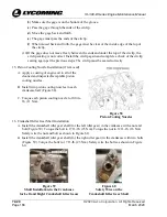
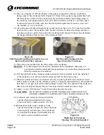
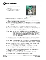
Measure and cut a total of four continuous lengths of "00" silk threads (four for only one
crankcase half). Two of the lengths will extend along the entire length of the top of the
crankcase flange as shown in Figure 82, and two silk thread lengths will be shorter to
cover the distance shown on the bottom flange of the same crankcase half. Do not apply
silk thread pairs to both crankcase halves.
Figure 82
Area on the Crankcase Flange to Apply
the POB Sealant and Silk Thread
Figure 83
Placement of Silk Threads
AlongInside Edge of
Crankcase Flange
CAUTION
TO ENSURE CORRECT SEALING, MAKE SURE THE SILK
THREADS RUN THE LENGTH, AS A CONTINUOUS PIECE, OF
THE INSIDE OF THE CRANKCASE FLANGE (FIGURE 82) AND
THERE ARE NO BREAKS IN THE ANY OF THE THREADS.
BREAKS IN THE SILK THREAD CAN CAUSE THE CRANKCASE
TO LEAK. MAKE SURE THE THREADS DO NOT CROSS OVER OR
LAY OVER EACH OTHER (FIGURE 82) OR COVER A HOLE IN
THE CRANKCASE FLANGE.

