IO-390-D Series Engine Maintenance Manual
72-20
© 2020 Avco Corporation. All Rights Reserved
Page 170
March 2020
IO-390-D Series Engine Maintenance Manual
(2)
Turn the propeller governor idler gear 90°. Record
backlash. Remove and insert the shim at 90
intervals. Record the reading of each backlash check.
(3)
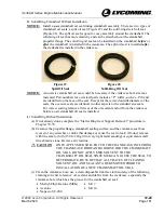
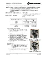
During assembly, to complete a check of the high
limit backlash, try to insert a shim between the
spacer and crankcase.
C.
Propeller Governor Set Screw Installation
NOTICE:
To ensure that there is adequate material in the
set screw hole to peen on top of the set screw,
use a new set screw that is shorter than the one
previously removed. A smaller diameter center
punch could be necessary. Refer to Figure 70.
(1)
Apply a light coat of Loctite
®
290
™
or equivalent to
the new set screw. Wipe away any excess Loctite
®
290
™
or equivalent with a clean lint-free cloth.
(2)
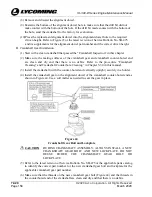
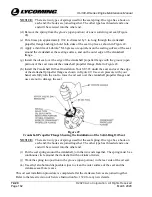
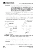
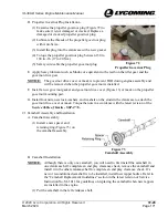
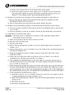
Install the set screw into the crankcase (Figure 70).
Align the idler gear shaft with the set screw to
enable the set screw to lock into the indentation in
the idler gear shaft to hold the idler gear shaft in
place.
(3)
Torque the set screw 32 to 38 in.-lb. (3.6 to 4.3 Nm).
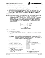
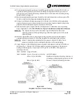
Figure 69
Shim Between Spacer and
Crankcase – Backlash Check
Figure 70
Set Screw Location
(4)
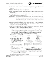
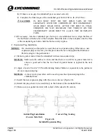
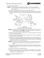
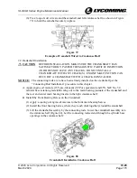
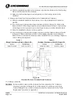
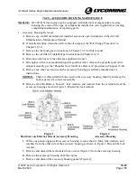
Use a smaller center punch (peening tool) with a 3/32-inch (2.38 mm) diameter at an
approximate 50°/60° angle to peen the threads of the hole at the top of the taper above the
set screw to prevent the set screw (as shown in Figure 71) from backing out.
Figure 71
Center Punch (Peening Tool) for Set Screw


