IO-390-D Series Engine Maintenance Manual
72-20
© 2020 Avco Corporation. All Rights Reserved
Page 176
March 2020
IO-390-D Series Engine Maintenance Manual
(3)
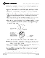
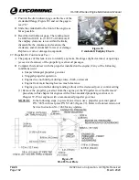
Press two lengths of "00" silk threads in the gasket compound on the top and bottom
flange sides (of the crankcase half) (Figure 82) firmly in the gasket compound where both
silk threads are oriented in the area between the bolt holes and the inside flange edge of
the crankcase half (approximately between 0.020 to 0.040 in. (0.508 to 1.106 mm) apart
as shown in Figure 83. Make sure that the silk thread lengths do not touch or cross over
one another or cover a bolt hole.
(4)
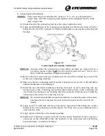
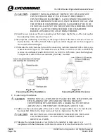
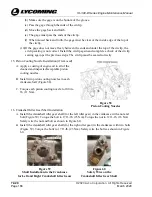
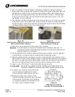
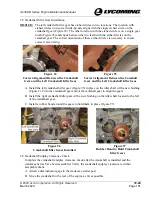
All continuous silk thread lengths must extend not more than ¼-in. (6.35 mm) beyond the
front and rear end of the crankcase half. Figure 84 shows the thread overhang extension
into the seal groove on the front end of the crankcase half. Figure 85 shows the silk thread
overhang extending from the rear of the crankcase half.
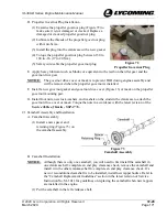
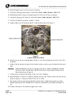
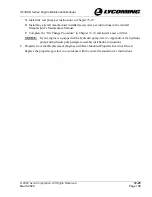
Figure 84
Silk Thread Extending into Seal Groove on
the Front End of the Crankcase
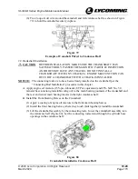
Figure 85
Silk Thread Extending into the
Rear End of the Crankcase
(5)
Wipe all excess sealant from the inner edges of the crankcase.
NOTICE:
If a
solid-ring stretch oil seal was installed on the crankshaft, make sure it is
positioned toward the crankshaft flange and does not touch either crankcase half
when the crankcase is assembled.
(6)
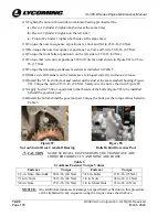
Lift the right half of the crankcase while keeping the halves parallel, lower the right half
of the crankcase over and onto the left crankcase half for the studs to align.
(7)
When the crankcase halves are aligned correctly, tap the right half of the crankcase with a
rubber mallet to make sure the crankcase halves are aligned and mated firmly all around and
that there are no gaps between the mating flange surfaces. Do not continue if the crankcase
halves are not aligned. Repeat the previous steps until the crankcase halves align.
(8)
Apply a coat of #2 Permatex
®
to the thru-studs at the dowel section.
CAUTION
BE SURE TO LUBRICATE THE CRANKCASE THRU-STUDS TO
ENSURE CORRECT FASTENING OF THE CRANKCASE HALVES.
(9)
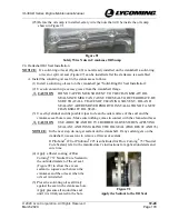
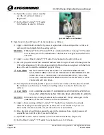
Lubricate each crankcase thru-stud with the
specified lubricant identified in the latest
revision of Service Instruction No. SI-1029.
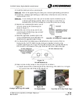
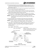
(10)
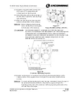
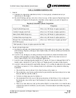
Install thru-studs on the crankcase in the
specified locations in Figure 86 where the studs
extend equally on both sides of the crankcase.
(An optional Crankcase Thru-Stud Driver ST-
317 can be used to install thru-studs.)
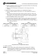
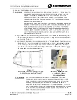
Figure 86
Right Side of Crankcase
Showing Thru-Studs Installed

