IO-390-D Series Engine Maintenance Manual
72-20
© 2020 Avco Corporation. All Rights Reserved
Page 154
March 2020
IO-390-D Series Engine Maintenance Manual
Connecting Rod Inspection Checklist for IO-390-D Series Engines (Cont.)
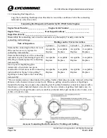
Connecting Rod Bearing and Crankshaft Clearance
To complete this inspection:
NOTICE:
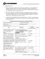
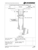
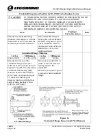
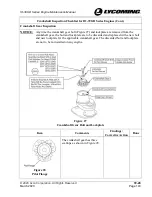
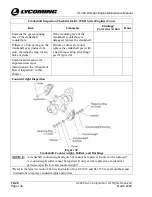
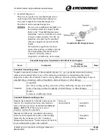
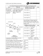
For this inspection the connecting rods, bearings, connecting rod bolts, and nuts
(Figure 35) are assembled, but not installed on the crankshaft.
1.
Assemble and torque each connecting rod with acceptable bearings per instructions in the
“Connecting Rod Installation” section in this chapter.
2.
Measure the inside diameter of the bearing in each connecting rod and record the
measurement below.
3.
Measure the crankshaft diameter at the crankpin journal for each connecting rod and record
the measurement below.
4.
Subtract the crankshaft diameter at the crankpin journal from the inside diameter of the
bearings for each connecting rod to calculate the connecting rod bearing and crankshaft
clearance. Record the measurement below.
5.
Compare the connecting rod bearing and crankshaft clearance to the acceptable clearance
measurement in the latest revision of the
Service Table of Limits - SSP-1776
.
6.
Remove and discard the connecting rod bolts and nuts from the connecting rod assembly.
7.
If the connecting rod bearing and crankshaft clearance is within limits, the connecting rod
bearings are acceptable.
8.
If the connecting rod bearing and crankshaft clearance is not within limits, the connecting
rod bearings must be replaced with oversize bearings to bring the clearance within
acceptable limits.
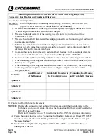
Cylinder
Inside Diameter
of the Bearings
Crankshaft Diameter at
the Crankpin Journal
Connecting Rod Bearing
and Crankshaft Clearance
Cylinder 1
Cylinder 2
Cylinder 3
Cylinder 4
11.
Connecting Rod Bushing Replacement
NOTICE:
Replace the connecting rod bushing if it is damaged or if the inner diameter of the
bushing is worn beyond service limit per the Connecting Rod Inspection Checklist for
IO-390-D Series Engines.
Refer to the latest revision of Service Instruction No. 1575 for additional information.
A.
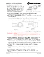
Clamp the connecting rod on the Connecting Rod Bushing Replacement Block (P/N 64597)
in such a manner that the small bushing in the rod is in alignment with the hole stamped
"Remove Bushing".
B.
Use the Connecting Rod Bushing Removal Drift P/N 64535 or equivalent to drive the
bushing out of the rod.

