IO-390-D Series Engine Maintenance Manual
© 2020 Avco Corporation. All Rights Reserved
72-70
March 2020
Page 249
IO-390-D Series Engine Maintenance Manual
(4)
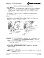
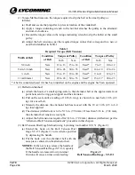
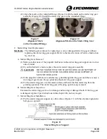
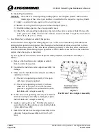
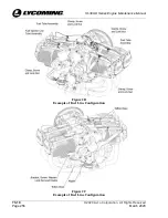
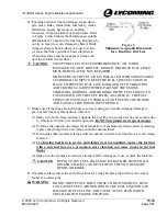
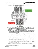
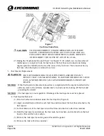
Align the mark on the crankshaft flange (Figure 9) with the mark on the starter ring gear
assembly (Figure 10). Install the starter ring gear on the crankshaft flange.
Figure 9
Alignment Mark
on the Crankshaft Flange
Figure 10
Alignment Mark on the Starter Ring Gear
9.
Starter Ring Gear Replacement
NOTICE:
The following procedure is for replacing a worn or damaged starter ring gear without
replacing the starter ring gear support. Refer to the latest revision of Service Instruction
No. SI-1141.
A.
Starter Ring Gear Removal
(1)
Make sure that none of the propeller bolt holes in the starter ring gear support are worn or
out-of-round.
(2)
If you find defective holes, replace the entire starter ring gear assembly.
CAUTION
DO NOT GRIND INTO THE STARTER RING GEAR SUPPORT. IF
YOU GRIND INTO THE STARTER RING GEAR SUPPORT, IT
MUST BE REPLACED.
(3)
If the propeller bolt holes are satisfactory, grind through the ring gear until there is only a
thin ring of gear metal. Do not grind into the starter ring gear support.
(4)
Put the starter ring gear on a flat metal surface and break the thin metal ring from the
grinding operation. The starter ring gear will spring open for easy removal.
B.
Starter Ring Gear Inspection
Examine the starter ring gear face for damage and missing or damaged teeth. If the ring gear
is damaged, replace it per instructions in this chapter. Do not use it again.
C.
Starter Ring Gear Installation
(1)
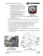
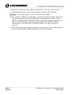
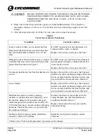
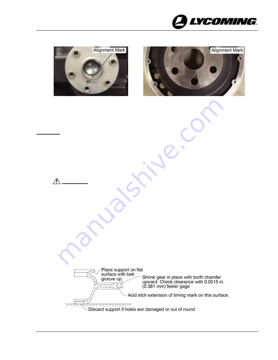
Put the starter ring gear support on a flat surface (Figure 11) with the alternator/generator
belt groove upward.
Figure 11
Starter Ring Gear Support

