IO-390-D Series Engine Maintenance Manual
© 2020 Avco Corporation. All Rights Reserved
72-30
March 2020
Page 193
IO-390-D Series Engine Maintenance Manual
NOTICE:
The orifice size of the differential compression tester is critical for consistent and
meaningful cylinder analysis. A specific orifice size of 0.040 in. diameter (No. 60
drill) x 0.250 in. long, with entrance angle of 59°/60° supplies an acceptable
calibrated leak rate. Larger orifice sizes can decrease the effectiveness of identifying
problems.
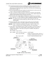
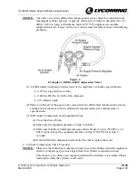
Figure 2
Example of a Differential Compression Tester
(1)
All differential compression testers must be in compliance with these specifications:
•
0.250 in. long restrictor orifice
•
0.040 in. ID (No. 61 drill) orifice diameter
•
60° entrance angle
(2)
Make sure that all of the gages to be connected to the differential compression tester are
calibrated in accordance with the differential compression tester’s manufacturer’s
specifications.
(3)
Differential Compression Test Equipment Check:
(a)
Close the shut-off valve.
(b)
Make sure the regulated pressure is 80 psi (552 kPa).
(c)
Make sure that the cylinder pressure gage shows 80 psi (± 2 psi) (552 kPa (± 14
kPa)), while it keeps the regulated pressure at 80 psi (552 kPa) for at least 5
seconds.
(d)
If the differential compression tester fails this check, replace the tester.
C.
Cylinder Compression Check Procedure
NOTICE:
Make sure the differential compression tester has been calibrated and the equipment
check is complete per previous steps before this cylinder compression check.
This check is to be done on an engine installed in the airframe or test stand without
interruption while the cylinder is still warm.

