IO-390-D Series Engine Maintenance Manual
© 2020 Avco Corporation. All Rights Reserved
72-20
March 2020
Page 165
IO-390-D Series Engine Maintenance Manual
(3)
Install the roller pair in the counterweight.
NOTICE:
Refer to the applicable parts catalog
for counterweight bushing part numbers
(4)
Install new counterweight bushings per instructions in the latest revision of Service
Instruction No. 1143.
NOTICE:
A new circlip pair and a new pair of washers must be installed on each
counterweight during assembly. Refer to the latest revision of Service
Instruction No. SI-1535 to identify the correct P/N for the new circlips.
(5)
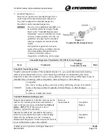
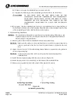
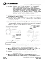
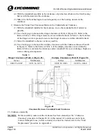
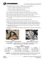
Install a new counterweight washer in each
of the two holes on the counterweight as
shown in Figure 53.
(6)
Install the new circlip on one side of each
counterweight with the sharp edge outward
as shown in Figure 53.
(7)
Install the applicable counterweight on the
correct crankshaft lobe and configuration as
identified in the applicable parts catalog
Figure 53
Assembly of Circlips in Counterweight
(8)
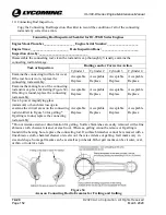
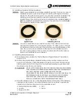
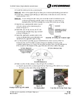
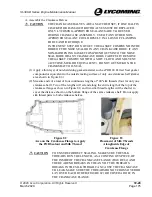
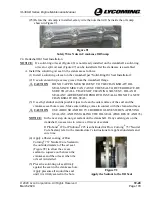
Use the specified Lycoming gage set identified in the latest revision of Service
Instruction No. SI-1535. Make sure the circlips are installed correctly on the
counterweight (Figure 53). Figure 54 shows the location of the A and B dimensions.
Dimension A is the diameter of the gage. Dimension B is the width of the gage.
Figure 54
A and B Dimensions
(9)
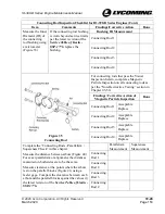
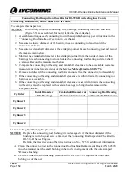
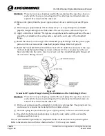
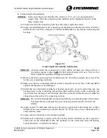
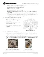
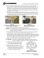
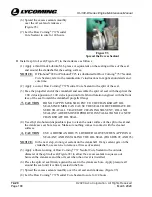
Make sure the circlip seating is correct (Figure 56) as follows:
(a)
Install one end of the counterweight Circlip Check Gage, P/N 64892-2 or -3 (Figure
55). between the ends of the circlip (Figure 57).
Figure 55
Circlip Check Gage P/N 64892
Figure 56
Circlip Installed
Figure 57
Insertion of Circlip Check Gage

