IO-390-D Series Engine Maintenance Manual
72-20
© 2020 Avco Corporation. All Rights Reserved
Page 182
March 2020
IO-390-D Series Engine Maintenance Manual
C.
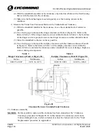
Position the dial indicator gage on the face of the
crankshaft flange (Figure 98) and set the gage to
read “0.”
D.
Slide the crankshaft to the front of the engine as
far as possible.
E.
Read the dial indicator gage. The reading must
be 0.009 and 0.021 in. (0.229 To 0.660 mm). If
the endplay clearance is not within the limits,
disassemble the crankcase and examine the
crankcase and/or crankshaft for wear or damage.
Replace a worn or damaged component.
Figure 98
Crankshaft Endplay Check
27.
Propeller Oil Control Leak Test
A.
The purpose of this leak test is to identify any leaks, blockages (tight clearance) or openings
(excessive clearance) of the propeller governor oil passages.
B.
Complete this leak test (with the propeller installed on the engine) if any of the following
conditions occur:
•
Suspect damaged propeller governor
•
Sluggish propeller operation
•
Engine does not hold rpm during cruise, climb, or descent
•
Engine front main bearing has too much clearance
•
Engine goes into feather during landing rollout with a decreased power control setting
(1)
Remove the propeller governor from the engine per the “Propeller Governor Removal”
procedure in this chapter for engines with a front-mounted propeller governor or in
Chapter 72-25 for engines with a rear-mounted propeller governor.
NOTICE:
In the following steps, to prevent an air leak, use a propeller governor gasket
P/N 72053 with test plate P/N ST-483 (Figure 99). Refer to the latest revision of
Service Instruction No. 1462 for any updates.
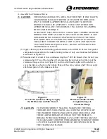
Figure 99
ST-483 Test Plate

