IO-390-D Series Engine Maintenance Manual
© 2020 Avco Corporation. All Rights Reserved
72-70
March 2020
Page 245
IO-390-D Series Engine Maintenance Manual
(c)
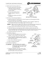
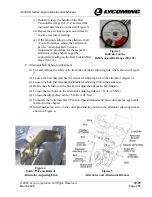
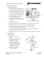
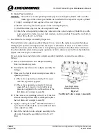
Quickly release the handle of the Belt
Tension Dial Gage (ST-131) and read the
indicated belt tension on the dial (Figure 3).
(d)
Repeat the previous steps several times to
ensure an accurate reading.
(e)
If the tension reading on the alternator belt
is out of tolerance, adjust the belt tension
per the “Alternator Belt Tension
Adjustment” procedure for the respective
alternator in this chapter to get the
appropriate reading on the Belt Tension Dial
Gage (ST-131).
Figure 3
Indicator on the
Belt Tension Dial Gage (ST-131)
C.
Alternator Belt Tension Adjustment
(1)
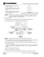
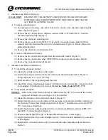
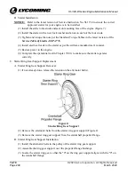
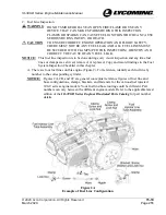
Cut and remove the safety wire from the alternator adjusting link where shown in Figure
4.
(2)
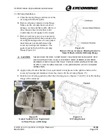
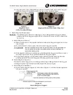
Loosen the bolt that attaches the alternator adjusting link to the alternator (Figure 5).
(3)
Loosen the bolt that attaches the alternator adjusting link to the crankcase.
(4)
Rotate the alternator on the bracket to adjust the alternator belt tension.
(5)
Torque the two bolts on the alternator adjusting link to 17 ft.-lb. (23 Nm).
(6)
Torque the idler pulley nut to 75 ft.-lb. (101 Nm).
(7)
Complete the “Alternator Belt Tension Check/Adjustment” procedure per the applicable
method in this chapter.
(8)
Install new safety wire on the cotter pins and two bolts on the alternator adjusting link as
shown in Figure 4.
Figure 4
Safety Wire on Bolts of
Alternator Adjusting Link
Figure 5
Alternator and Alternator Bracket

