IO-390-D Series Engine Maintenance Manual
72-10
© 2020 Avco Corporation. All Rights Reserved
Page 120
March 2020
IO-390-D Series Engine Maintenance Manual
Table 2 (Cont.)
Sequence of Engine Assembly Procedures
Step
Reference
Step
Reference
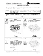
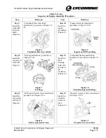
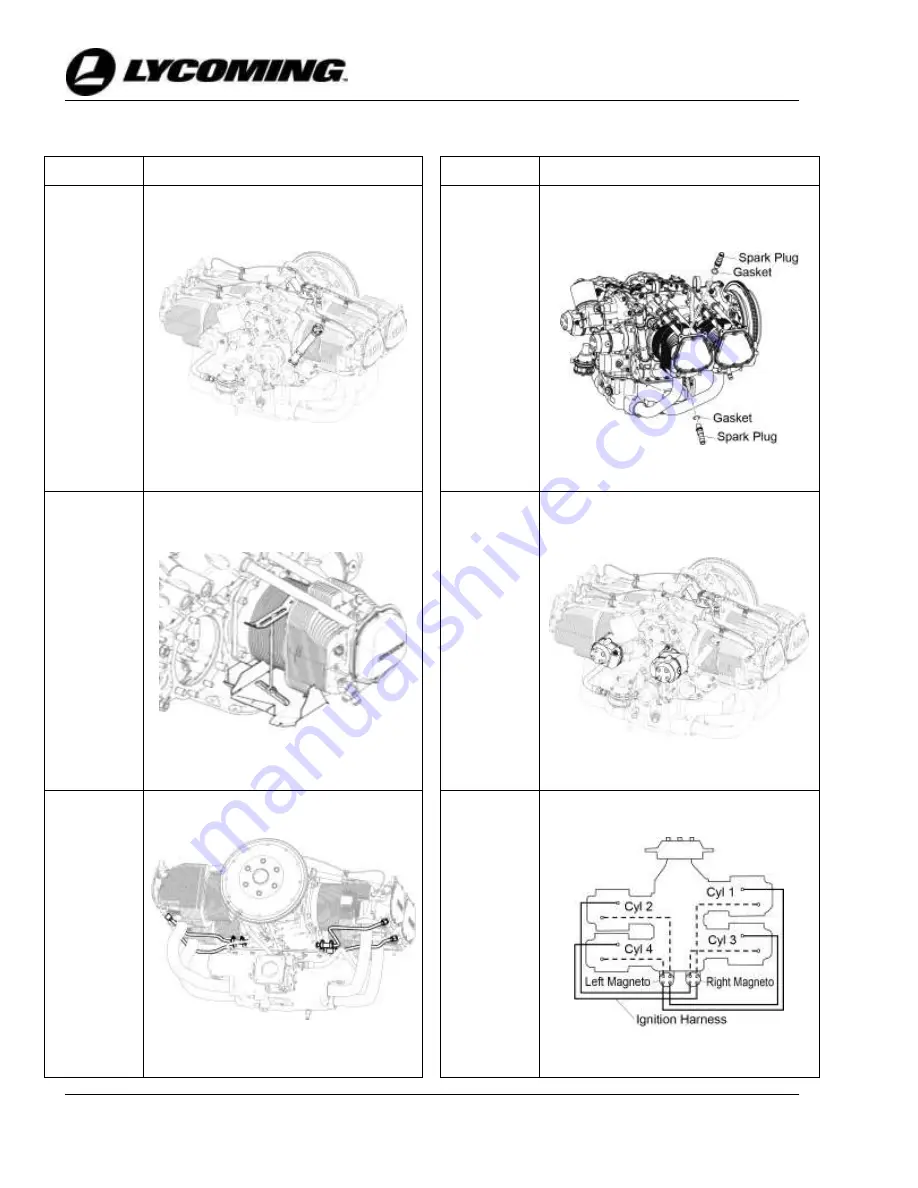
Step 25
“Oil Level Gage Tube and Assembly
Installation” procedure in Chapter 72-
50
Step 28
“Spark Plug Gap Setting” and “Spark
Plug Installation” procedures in
Chapter 74-20.
Install the
oil level
gage
assembly
and oil level
gage tube
(Figure 24).
Examine,
set the gap,
and install
all spark
plugs (one
in the top
and bottom
of each
engine
cylinder)
(Figure 27).
Figure 24
Oil Level Gage Tube
Figure 27
Spark Plugs
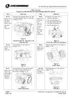
Step 26
“Intercylinder Baffle Installation”
procedure in Chapter 72-30
Step 29
Install the
Lycoming
Electronic
Ignition
System
modules or
magnetos
on the
engine
(Figure 28).
“EIS Installation” or “Magneto
Installation” procedure in Chapter 74-
30
Install inter-
cylinder
baffles
(Figure 25).
Figure 25
Intercylinder Baffle
Figure 28
EIS/Magnetos
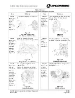
Step 27
Attach four
new oil
drain tubes,
one on each
engine
cylinder
head and
the
crankcase
(Figure 26).
“Oil Drain Tube Installation”
procedure in Chapter 72-30
Step 30
Install the
ignition
harness on
the engine
(Figure 29).
“Ignition Harness Installation”
procedure in Chapter 74-20
Figure 26
Oil Drain Tubes
Figure 29
Ignition Harness

