IO-390-D Series Engine Maintenance Manual
© 2020 Avco Corporation. All Rights Reserved
72-20
March 2020
Page 159
IO-390-D Series Engine Maintenance Manual
(7)
Apply a small amount of Loctite
®
Food-Grade AA anti-seize lubricant or equivalent to
the bottom three or four threads of the new crankshaft gear bolt. Wipe away any excess
lubrication.
NOTICE:
Do not bend the tab on the lockplate yet.
(8)
Install a new lockplate and new crankshaft gear bolt with the part number on the top of
the bolt head.
(9)
Initially torque the crankshaft gear bolt (regardless of size) to 125 in.-lb (14.12 Nm)
torque. Do not bend the lockplate at this time.
CAUTION
FOR CORRECT ENGINE OPERATION, THE CRANKSHAFT GEAR
MUST BE INSTALLED CORRECTLY WITH NO GAP BETWEEN
THE MATING SURFACES OF THE COUNTERBORED-END OF THE
CRANKSHAFT AND THE CRANKSHAFT GEAR PILOT FLANGE
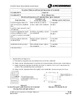
(FIGURE 45).
(10)
With a hammer and brass drift, tap lightly around the pilot flange of the crankshaft gear
and listen for sharp solid sounds from the hammer blows that would indicate that the
crankshaft gear is seated against the crankshaft.
(11)
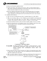
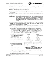
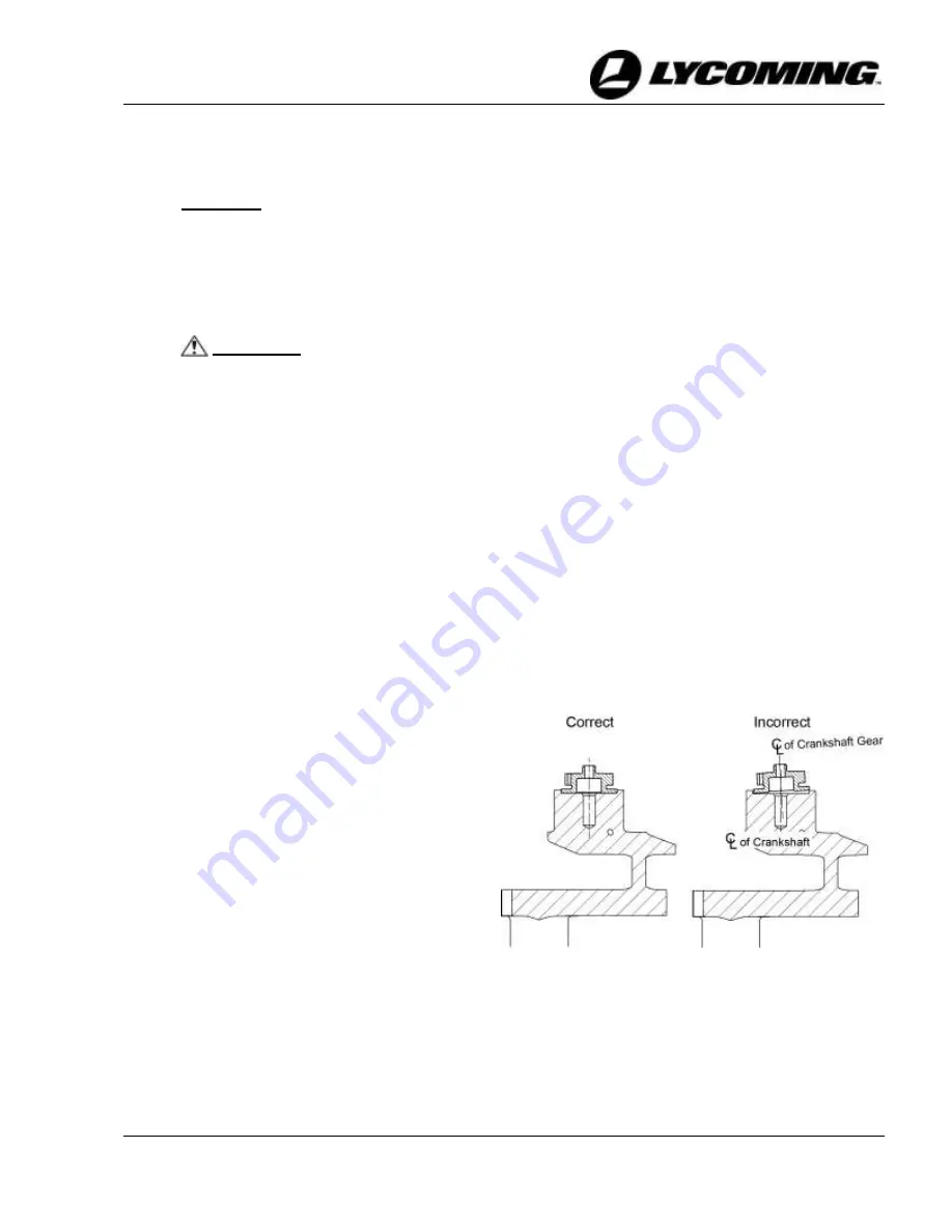
Make sure the crankshaft gear seats firmly and perpendicularly flat and straight (not at a
slanted angle) against the crankshaft as shown in Figure 45:
(a)
Try to insert a pointed 0.001 in. (0.025 mm) feeler gage or shim between the pilot
flange of the crankshaft gear and crankshaft counterbore at each of the three scallops
on the pilot flange of the crankshaft gear. The feeler gage must NOT fit between the
two surfaces at any location. There must not be any gap or clearance between the
crankshaft counterbored end and the pilot flange of the crankshaft gear.
(b)
If clearance is found, remove the
crankshaft gear bolt, lockplate,
and crankshaft gear.
(c)
Make sure the mating surfaces
of the crankshaft gear and
crankshaft counterbore are clean
and dry and that there is no
debris.
(d)
Reinstall the crankshaft gear,
lockplate, and crankshaft gear
bolt.
(e)
Torque the crankshaft gear bolt
to 125 in.-lb (14.12 Nm).
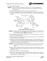
Figure 45
Seating of the Crankshaft Gear Against the
Counterbored End of the Crankshaft
(f)
Try to put a pointed 0.001 in. (0.025 mm) feeler gage or shim stock between the pilot
flange of the crankshaft gear and crankshaft counterbore at each of the three scallops
on the pilot flange of the crankshaft gear.
(g)
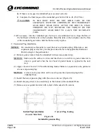
If there is still a gap, replace the crankshaft gear.

