IO-390-D Series Engine Maintenance Manual
72-30
© 2020 Avco Corporation. All Rights Reserved
Page 200
March 2020
IO-390-D Series Engine Maintenance Manual
NOTICE:
If one valve is sticking, examine all intake and exhaust valves on all of the engine
cylinders.
The exhaust valve and guide must be examined to measure valve stem movement to identify
excessive wear (bell-mouthing) of the exhaust valve guide and carbon build-up between the
valve guide and valve stem which can cause valve sticking
Refer to the latest revision of Service Bulletin No. SB-388, Service Instruction No. SI-1485, and
Service Letter L197 for additional details.
NOTICE:
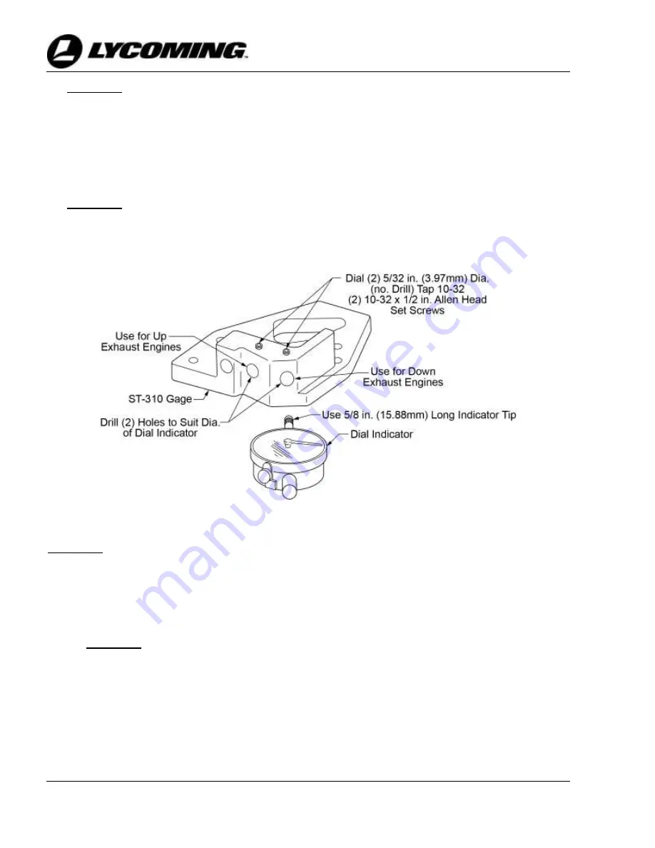
The Gage (ST-310) is used to examine angular-type valves on engine cylinders.
Although Gage (ST-310) and a feeler gage can be used to measure valve stem
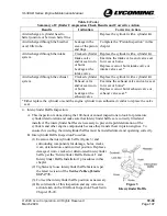
movement, a modified Gage (ST-310) (Figure 4) and a dial indicator are a faster and
easier means to measure valve stem movement, valve guide wear, and carbon build-
up per this procedure.
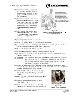
Figure 4
Details for Modifying Tool P/N ST-310
NOTICE:
Do not intermix valve and cylinder components between cylinders. Re-install
serviceable parts in the same cylinder.
A.
Examine the exhaust valve and guide on each cylinder as follows:
(1)
Disable all power to the engine.
(2)
Make sure the engine is cool.
NOTICE:
A silicone rocker box cover gasket can be reused if it is not damaged.
(3)
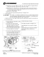
Remove the screws, rocker box cover (Figure 5) and gasket from the cylinder head.
Discard the gasket.
(4)
Remove the nuts, lock washers, rocker shaft cover, and rocker shaft cover gasket. Discard
the lock washers and rocker shaft cover gasket.
(5)
Remove the valve rocker shaft, valve rocker shaft bushing, rocker assembly, and washer.
(6)
Remove the valve stem cap from the exhaust valve.

