IO-390-D Series Engine Maintenance Manual
© 2020 Avco Corporation. All Rights Reserved
72-30
March 2020
Page 201
IO-390-D Series Engine Maintenance Manual
(7)
Remove and examine the valve stem keys which tend to wear in uniform distinctive
patterns. Replace worn or damaged valve stem keys. If the keys do not need to be
replaced, install them in the same position from where they were removed.
CAUTION
DO NOT MIX PLUNGER ASSEMBLIES WITH DIFFERENT PART
NUMBERS IN THE SAME ENGINE. DIFFERENT PLUNGERS
HAVE VARYING LEAK DOWN RATES WHICH CAN CAUSE
INCORRECT ENGINE OPERATION.
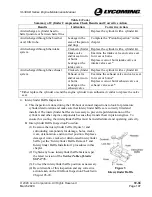
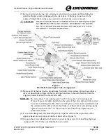
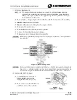
Figure 5
IO-390-D Series Engine Valve Components
(8)
Remove all of the push rods, shroud tubes, hydraulic lifter sockets, plunger assemblies,
sleeve, shroud tube springs, washers, and upper and lower shroud tube seals from the
engine cylinder. Discard the shroud tube seals.
NOTICE:
Do not confuse “valve spring seats” with “valve seats,” valve spring seats
(Figure 5) are metal disks installed on the ends of the valve springs in the rocker
box and are field replaceable. Valve seats (Figure 5, View A) are installed inside
the cylinder as the surface where the intake or exhaust valve rests during engine
operation when that valve is closed. Valve seats only can be replaced by an
authorized vendor.
(9)
Use a cloth dampened with mineral spirits to wipe the oil from the top surface of the
upper exhaust valve spring seat on the exhaust valve (Figure 5).
(10)
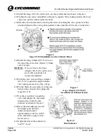
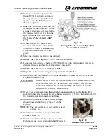
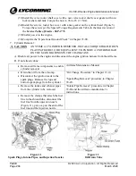
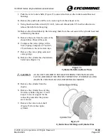
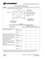
Loosen the screws identified in Figure 6 to prevent the screws from touching the Gage
Adapter (ST-310-9) when installed on the valve stem.

