IO-390-D Series Engine Maintenance Manual
72-20
© 2020 Avco Corporation. All Rights Reserved
Page 138
March 2020
IO-390-D Series Engine Maintenance Manual
(c)
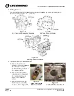
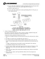
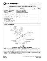
Use the Arbor Press Spindle and Counterweight Bushing Driver ST-92 to press both
bushings out from one side of the counterweight. Refer to Figure 23.
(d)
Turn the counterweight over.
(e)
Use the Arbor Press Spindle and Counterweight Bushing Driver ST-92 to press out
the remaining bushings.
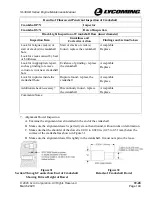
Figure 23
Counterweight Bushing Removal/Installation
Using the Counterweight Fixture Assembly ST-93
and the Counterweight Bushing Driver ST-92
5.
Crankcase Dimensional Inspection
The crankcase dimensional inspection is done to make sure that the crankshaft bearings and
camshaft slots formed by the crankcase are within allowable limits.
Complete the crankcase dimensional inspection as follows:
A.
Install new crankshaft bearings at all main bearing locations in the crankcase halves (Figure
12).
B.
Assemble the crankcase halves and install thru-studs (Figure 3).
C.
Use washers and nuts on the thru-studs to install the Torque Hold Down Plates (ST-222,
Figure 83) at the cylinder pads over the thru-studs. Tighten the nuts only finger tight at this
time.
(1)
Make sure that the plates remain parallel with the cylinder decks of the crankcase.
(2)
Temporarily torque the nuts to 300 in.-lb. (34 Nm).
D.
Attempt to insert a 0.004 in. tapered feeler gage between the crankcase mating faces. If the
gage will not enter between the crankcase parting faces, the crankcase is considered
satisfactory.
E.
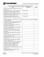
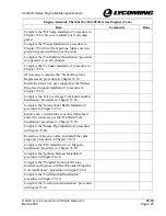
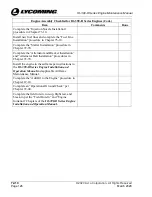
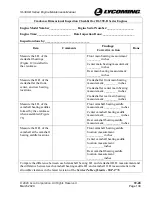
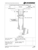
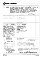
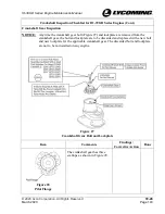
Make a copy and complete the Crankcase Dimensional Inspection Checklist for IO-390-D
Series Engines.
F.
Remove the nuts, washers, and Torque Hold Down Plates (ST-222) and separate the
crankcase halves.

