


159
Set the Waveform Position (Variable Function)
Variable Function Settings per Channel
Procedure
Press the
CHAN
key to open the Channel screen, and then select the
[Each Ch]
sheet.
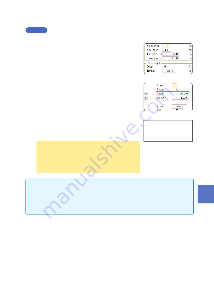
1
Enable the Variable function.
Move the cursor to
[Variable]
, and select
[On].
1
2
3
4
To reset the settings
Select
[Reset]
to return the
settings to their default values.
2
Set the display range per division
Move the cursor to
[Range(div)]
, and enter a numerical value.
(Measurement units depend on the measurement mode of the module.)
(When this is changed, the upper/lower limit values for the display also
change accordingly.)
3
Set the waveform zero position to display on the vertical axis
(vertical axis).
Move the cursor to
[Zero pos%]
, and enter a numerical
[%]
value.
(When this is changed, the upper/lower limit values for the display also
change accordingly.)
4
(When setting upper and lower values)
Move the cursor to
[Upper]
and
[Lower]
, and specify the values.
(When these are changed, the display range and zero position values
also change accordingly.)
•When upper and lower values are set, waveforms can be displayed
at full span on the screen.
•Depending on the scaling setting, the upper and lower display
values may be less than 1. In such cases, set
[Variable]
to
[On]
then select
[Auto Set]
.
Easy-to-read upper and lower limit values are set based on the
current set values.
• For information on numeric input, refer to “8.1.3 Alphanumeric Input” (p. 143).
• The
[Unit List]
sheet accessed from the Channel screen also lets you turn the Variable function On
or Off individually for each channel.
• By using the Scaling and Variable functions together, the full span of a sensor's output can be
• When Scaling is enabled, values are displayed in scaling units. When these settings are changed, the
numerical values indicating the display range on the level monitor are changed accordingly.
8
Utility Functions
Summary of Contents for MR8827
Page 19: ...14 Operation Precautions ...
Page 81: ...76 Start and Stop Measurement ...
Page 111: ...106 Manage Files ...
Page 125: ...120 Miscellaneous Printing Functions ...
Page 143: ...138 View Block Waveforms ...
Page 191: ...186 Setting Output Waveform Parameters ...
Page 291: ...286 FFT Analysis Modes Measurable Ranges With Octave Analysis 1 1 OCT 1 3 OCT ...
Page 292: ...287 FFT Analysis Modes 1 1 OCT 1 3 OCT 13 FFT Function ...
Page 293: ...288 FFT Analysis Modes 1 1 OCT 1 3 OCT ...
Page 295: ...290 FFT Analysis Modes ...
Page 309: ...304 Editor Command Details ...
Page 387: ...382 Module Specifications ...
Page 405: ...400 Dispose of the Instrument Lithium Battery Removal ...
Page 431: ...A26 FFT Definitions ...
Page 436: ......


