


160
Set the Waveform Position (Variable Function)
Variable Function Settings for All Channels
Procedure
Press the
DISP
key
to open the Waveform screen, and then press the
CH.SET
key to open the display range window.
1
Enable the Variable function.
Move the cursor to
[Variable]
, and select
[On]
.
1
2
2
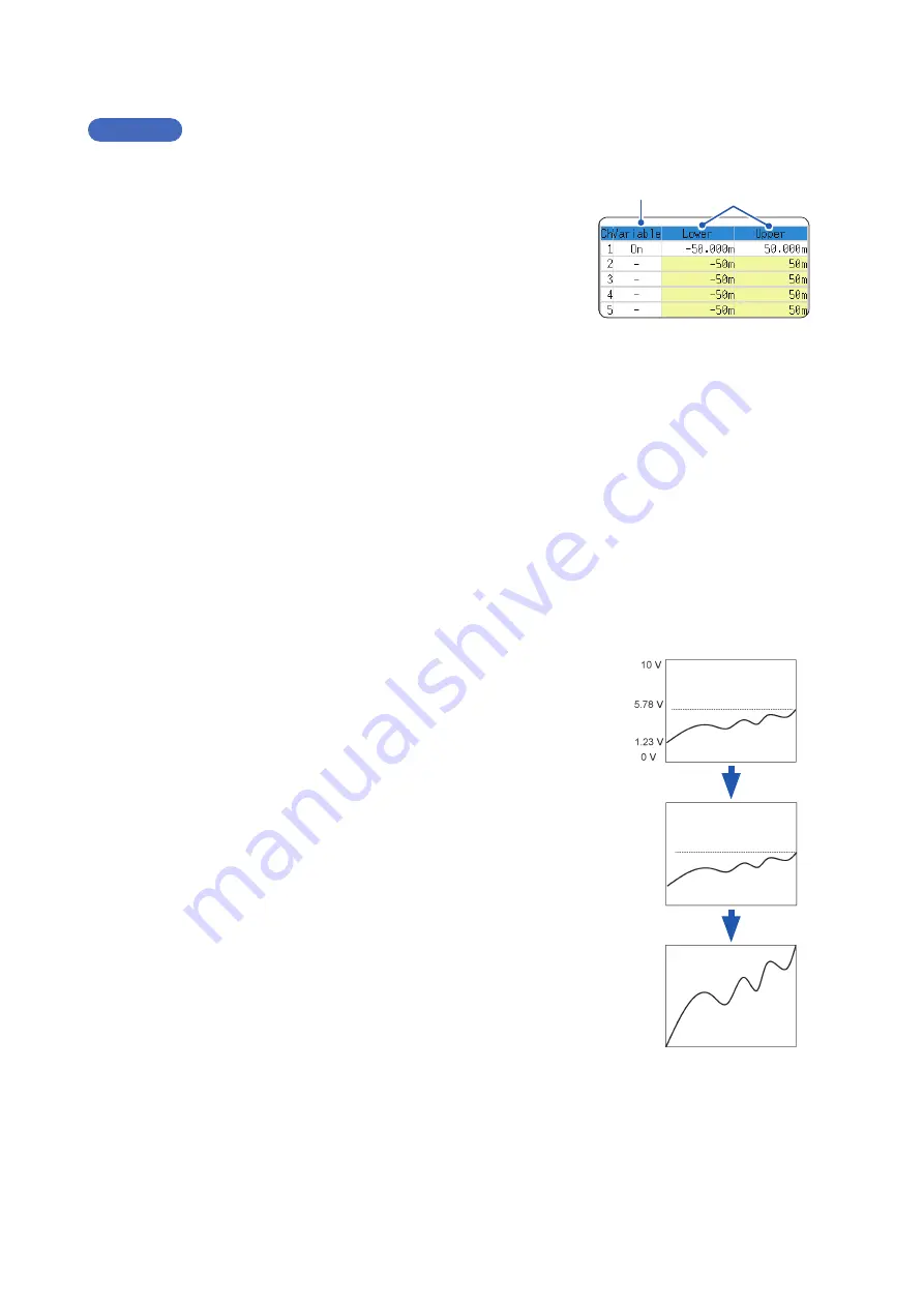
Set the upper and lower limits.
Move the cursor to
[Upper]
and
[Lower]
and enter numerical
values.
When Using the Scaling and Variable Functions Together
When auto-correction of the variable function (p. 307) is enabled (On)
(Default setting)
The Variable function settings change according to Scaling and vertical axis (voltage axis) range settings.
Set Scaling before setting the Variable function.
If you change Scaling settings after enabling the Variable function, the Variable setting voltage is
automatically corrected so that the displayed size of waveforms is unchanged.
When auto-correction of the Variable function is disabled (Off)
Set the Variable function after setting Scaling.
If you set the Variable function first, enter post-scaling values (converted physical values).
To display the full span of output from a sensor
By using the Scaling and variable functions in combination, voltage from a sensor can be converted to the
physical units of the measurement object.
(Example)
Set Scaling as follows:
Scaling: Decimal or exponent, Two-Point Setting
Units: A
Sensor Output (Input 1): 1.23 [V]→(Scale 1): 0 [A]
Sensor Output (Input 2): 5.78 [V]→(Scale 2): 10 [A]
(With Variable function Off)
Voltage from the sensor is displayed as voltage.
It is displayed with the vertical axis (voltage axis) range and at the zero
position set on the Channel settings window (
[Analog]
sheet).
The Variable function is set as follows:
Variable: On, Set Upper/Lower Limits
Lower Limit: 0 [A] Upper Limit: 10 [A]
The full span of output from the sensor is displayed.
0 A
10 A
0 A
10 A
Summary of Contents for MR8827
Page 19: ...14 Operation Precautions ...
Page 81: ...76 Start and Stop Measurement ...
Page 111: ...106 Manage Files ...
Page 125: ...120 Miscellaneous Printing Functions ...
Page 143: ...138 View Block Waveforms ...
Page 191: ...186 Setting Output Waveform Parameters ...
Page 291: ...286 FFT Analysis Modes Measurable Ranges With Octave Analysis 1 1 OCT 1 3 OCT ...
Page 292: ...287 FFT Analysis Modes 1 1 OCT 1 3 OCT 13 FFT Function ...
Page 293: ...288 FFT Analysis Modes 1 1 OCT 1 3 OCT ...
Page 295: ...290 FFT Analysis Modes ...
Page 309: ...304 Editor Command Details ...
Page 387: ...382 Module Specifications ...
Page 405: ...400 Dispose of the Instrument Lithium Battery Removal ...
Page 431: ...A26 FFT Definitions ...
Page 436: ......


