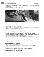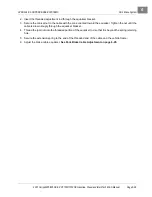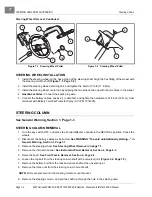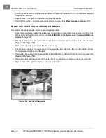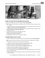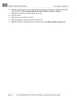
STEERING AND FRONT SUSPENSION
Rack and Pinion
Page 7-6
2007 Carryall 295/295 SE & XRT 1550/1550 SE Gasoline, Diesel and IntelliTach M & S Manual
7
Rack and Pinion Disassembly, Continued:
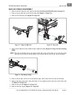
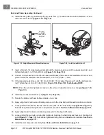
9. Install the universal joint on the pinion, and place a fork or a large open-end wrench under the universal
joint
(Figure 7-12, Page 7-6)
. Gently pry the pinion from the housing.
10. Remove the U-joint from the pinion.
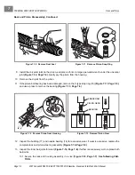
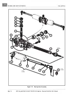
11. If the pinion ball bearing has been damaged, remove the C-type stop ring (16)
(Figure 7-11, Page 7-6),
and use a press to remove the bearing
(Figure 7-13, Page 7-6)
.
12. Inspect the bushing (17) and needle bearing (14) for excessive wear. If wear is excessive, replace the
complete rack and pinion steering assembly
(Figure 7-16, Page 7-8)
.
13. Inspect the inner ball joints for wear
(Figure 7-16, Page 7-8)
. If either is excessively worn, replace both
ball joints.
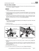
13.1. Secure the rack and housing assembly in a vise
(Figure 7-14, Page 7-7)
.
See following CAU-
TION.
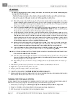
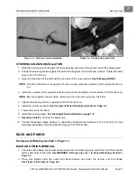
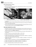
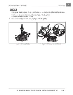
Figure 7-10 Remove Dust Seal
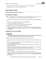
Figure 7-11 Remove Pinion Snap Ring
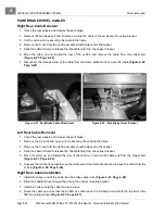
Figure 7-12 Remove Pinion from Housing
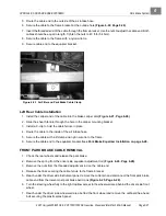
Figure 7-13 Remove Pinion Gear
4
16
PRESS RAM
PINION GEAR
BEARING
Summary of Contents for IntelliTach XRT 1550
Page 2: ......
Page 22: ...1...
Page 54: ...4...
Page 60: ...5...
Page 90: ...6...
Page 114: ...8...
Page 118: ...9...
Page 196: ...11A...
Page 290: ...11C...
Page 468: ...13C...
Page 490: ...14...
Page 498: ...15...
Page 548: ...16...
Page 560: ...Club Car R NOTES...
Page 561: ...Club Car R NOTES...
Page 562: ...Club Car R NOTES...
Page 563: ......


