HYDRAULIC ATTACHMENT SYSTEM
Electrical
Page 16-16
2007 Carryall 295/295 SE & XRT 1550/1550 SE Gasoline, Diesel and IntelliTach M & S Manual
16
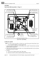
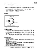
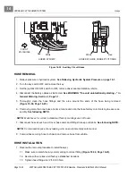
2. Check the following locations for no continuity with switch in the “rest” position and continuity with switch
in either the “extend” or “retract” position
(Figure 16-25, Page 16-15)
:
•
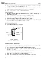
Between terminal 5 (orange wire w12) and terminals 4 and 6 (light green wires w22 and 23)
•
Between terminal 2 (red/white wire w82) and terminal 1 (gray wire w01)
•
Between terminal 2 (red/white wire w82) and terminal 3 (gray/white wire w57)
3. If switch does not work as stated in previous step, replace switch.
See Auxiliary Switch Removal on
page 16-16.
4. If switch does work as stated in step 2 and the auxiliary hydraulic feature still does not work, check the
following items:
•
Fuse.
•
Joystick ON/OFF switch.
•
Joystick switches.
•
Auxiliary control valves.
See Control Valves on page 16-21.
•
Continuity of the wires involved.
Auxiliary Switch Removal
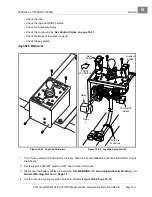
1. Turn the key switch OFF and remove the key. Place the Forward/Reverse handle in NEUTRAL. Chock
the wheels.
2. Set the joystick ON/OFF switch to OFF and remove both seats.
3. Disconnect the battery cables as instructed.
See WARNING “To avoid unintentionally starting...” in
General Warning, Section 1, Page 1-1.
4. Cut the wire tie securing joystick harness to chassis
(Figure 16-22, Page 16-11)
.
5. Remove four screws securing control box cover/joystick assembly and pull assembly out enough to
access the switch.
See Joystick Removal on page 16-11.
6. Ensure the wires are connected correctly and are tight. If they are not, rewire or tighten as necessary.
7. Unplug harness from switch
(Figure 16-22, Page 16-11)
. Note orientation of alignment notches
(Figure 16-25, Page 16-15)
. Squeeze tabs at each end of switch and push switch out the top of the con-
trol box cover.
Auxiliary Switch Installation
1. Orient alignment notches and insert switch into control box cover until fully seated
(Figure 16-25,
Page 16-15)
.
2. Connect harness plug to switch.
3. Install control box cover/joystick assembly and secure with the four screws.
4. Secure joystick harness to chassis with new wire tie
(Figure 16-22, Page 16-11)
.
5. Connect the battery cables, positive (+) cable first, and tighten the terminals to 144 in-lb (16 N·m). Coat
terminals with Battery Terminal Protector Spray (CCI P/N 1014305).
Summary of Contents for IntelliTach XRT 1550
Page 2: ......
Page 22: ...1...
Page 54: ...4...
Page 60: ...5...
Page 90: ...6...
Page 114: ...8...
Page 118: ...9...
Page 196: ...11A...
Page 290: ...11C...
Page 468: ...13C...
Page 490: ...14...
Page 498: ...15...
Page 548: ...16...
Page 560: ...Club Car R NOTES...
Page 561: ...Club Car R NOTES...
Page 562: ...Club Car R NOTES...
Page 563: ......


