


ELECTRICAL COMPONENTS: DIESEL VEHICLES
Reverse Warning Buzzer Limit Switch (If Equipped)
Page 12c-12
2007 Carryall 295/295 SE & XRT 1550/1550 SE Gasoline, Diesel and IntelliTach M & S Manual
12C
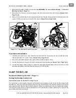
Reverse Warning Buzzer Limit Switch Installation
1. Install the reverse warning buzzer limit switch in the reverse order of removal.
2. Place the Forward/Reverse handle in the REVERSE position.
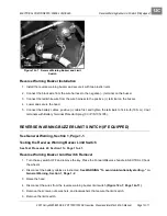
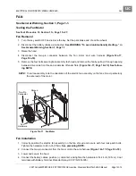
3. Tighten the limit switch mounting screws so that they are snug, but the limit switch can still be rotated in
the adjustment slot
(Figure 12c-8, Page 12c-12)
.
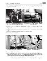
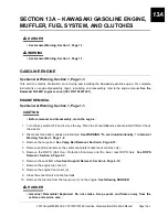
4. Rotate the limit switch so that the lobe on the Forward/Reverse handle activates the limit switch as shown
(Figure 12c-9, Page 12c-12)
.
5. Hold the limit switch in position and tighten the mounting screws and nuts to 4 in-lb (0.5 N·m).
See fol-
lowing CAUTION.
CAUT ION
• Do not overtighten the retaining nuts. If the nuts are overtightened, the limit switch could
become damaged.
6. Place the Forward/Reverse handle in NEUTRAL and then back to REVERSE to ensure that the limit
switch lever is being properly activated.
7. Connect the 18-gauge red and 18-gauge red/white wires to the limit switch.
8. Lower and secure the hood.
9. Connect the battery cables, positive (+) cable first, and tighten the terminals to 144 in-lb (16 N·m). Coat
terminals with Battery Terminal Protector Spray (CCI P/N 1014305).
10. Turn the key switch to the ON position. With the Forward/Reverse handle in REVERSE, the buzzer
should sound.
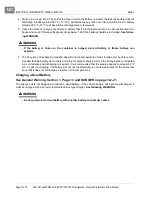
Figure 12c-8 Reverse Warning Buzzer Limit Switch
Adjustment Slot
Figure 12c-9 Reverse Warning Buzzer Limit Switch
(Properly Adjusted)
Summary of Contents for IntelliTach XRT 1550
Page 2: ......
Page 22: ...1...
Page 54: ...4...
Page 60: ...5...
Page 90: ...6...
Page 114: ...8...
Page 118: ...9...
Page 196: ...11A...
Page 290: ...11C...
Page 468: ...13C...
Page 490: ...14...
Page 498: ...15...
Page 548: ...16...
Page 560: ...Club Car R NOTES...
Page 561: ...Club Car R NOTES...
Page 562: ...Club Car R NOTES...
Page 563: ......


