DRIVETRAIN COMPONENTS
Transmission
Page 14-14
2007 Carryall 295/295 SE & XRT 1550/1550 SE Gasoline, Diesel and IntelliTach M & S Manual
14
TRANSMISSION INSTALLATION
See General Warning, Section 1, Page 1-1.
1. Apply a light coat of anti-seize to the front splined shaft of the transmission.
1. Ensure the base brackets are installed on the transmission and install the transmission on the engine
mounting plate while sliding the splined shaft into the front driveshaft.
2. Align the base bracket slots with the mounting holes in the engine mounting plate.
See following NOTE.
NOTE:
The right-angle lips on the base brackets should be positioned over each side of the engine mount-
ing plate.
If the transmission is new or the base brackets have been removed, leave the base brackets loose.
3. Secure the clutch inner cover to the engine and transmission with bolts and washers. Finger-tighten the
hardware.
Gasoline vehicles:
See Clutch Inner Cover Installation, Section 13b, Page 13b-40.
Die-
sel vehicles: See Clutch Inner Cover Installation, Section 13c, Page 13c-36.
See following NOTE.
NOTE:
Hole tolerances in the inner cover are very close in diameter to bolt sizes. The inner cover is used
to align the engine and transmission and is the primary support for the transmission.
Allow the inner cover plate to assist in aligning the engine and transmission.
4. Tighten the transmission body base flange-head bolt and flange-head locknut to 39 ft-lb (53 N·m).
5. If removed, install two new bolts, flat washers, and new flanged locknuts on the transmission base brack-
ets and engine mounting plate. Tighten the hardware to 21 ft-lb (29 N·m).
6. Connect the neutral sensing connector on the transmission to the wire harness
(Figure 14-19,
Page 14-13)
.
7. Secure the Forward/Reverse shifter cable ball socket to the ball stud on the transmission shifter arm
(Figure 14-24, Page 14-17)
.
See following NOTE.
8.
Honda Powered Gasoline vehicles:
Install the ground speed governor arm
(Figure 14-18,
Page 14-13)
.
8.1. Secure the governor cable from the engine to the governor arm.
See Governor Cable Installation,
Section 13b, Page 13b-20.
8.2. Secure the accelerator cable to the governor arm.
See Accelerator Cable Installation,
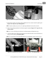
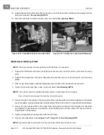
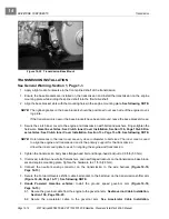
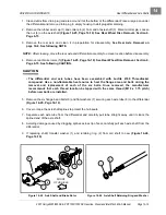
Figure 14-20 Transmission Base Mount
Summary of Contents for IntelliTach XRT 1550
Page 2: ......
Page 22: ...1...
Page 54: ...4...
Page 60: ...5...
Page 90: ...6...
Page 114: ...8...
Page 118: ...9...
Page 196: ...11A...
Page 290: ...11C...
Page 468: ...13C...
Page 490: ...14...
Page 498: ...15...
Page 548: ...16...
Page 560: ...Club Car R NOTES...
Page 561: ...Club Car R NOTES...
Page 562: ...Club Car R NOTES...
Page 563: ......


