TROUBLESHOOTING AND ELECTRICAL SYSTEM: KAWASAKI POWERED GASOLINE VEHICLES
Test Procedures
Page 11a-34
2007 Carryall 295/295 SE & XRT 1550/1550 SE Gasoline, Diesel and IntelliTach M & S Manual
11A
TEST PROCEDURE 25 – FUEL GAUGE
See General Warning, Section 1, Page 1-1.
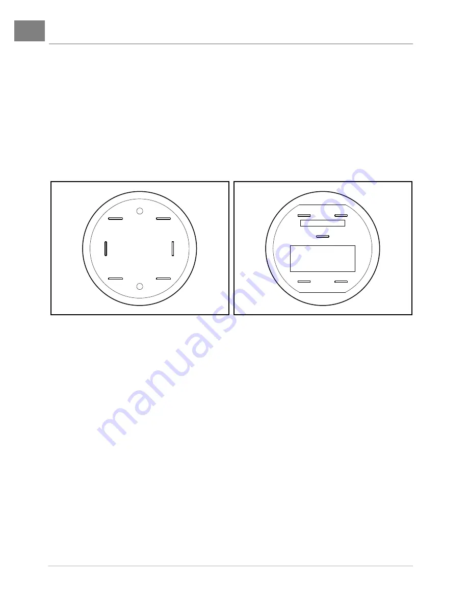
Two fuel gauges were used for model year 2007
(Figure 11a-29, Page 11a-34
and
Figure 11a-30,
Page 11a-34)
. The terminal configuration on the back of the gauge easily denotes the type. Follow the appro-
priate procedure. The early 2007 gauge has the orange wire connected to terminal 1 whereas late 2007 has
it connected to terminal 4 in the center of the gauge. In addition, the early 2007 gauge has one terminal (3) to
ground it whereas the late 2007 has two ground terminals (1 and 6) with a black jumper wire connecting them.
See following NOTE.
NOTE:
Keep the battery connected during this test procedure.
Test Procedure 25A – Fuel Gauge (Early 2007)
1. Turn the key switch OFF and remove the key. Place the Forward/Reverse handle in NEUTRAL. Chock
the wheels.
2. Raise the hood.
3. Disconnect the orange wire (w104) from the fuel gauge/hour meter.
4. Set a multimeter to 20 volts DC and place the red (+) probe on the positive (+) post of the battery. Place
the black (–) probe on the negative (–) post of the battery. Record the voltage reading.
5. Set a multimeter to 20 volts DC and place the red (+) probe on the (2) terminal of the fuel gauge/hour
meter where the blue wire (w25) is connected. Place the black (–) probe on the (3) terminal of the fuel
gauge/hour meter with the black wire (w22)
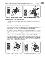
(Figure 11a-31, Page 11a-35)
.
6. Turn the key switch ON. The voltage reading should be the same as the battery voltage reading recorded
earlier. If not, check the continuity of the blue and black wires
(Figure 11a-31, Page 11a-35)
.
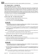
7. The orange wire should remain disconnected for this step. Place the black probe of the multimeter on the
(3) terminal of the fuel gauge/hour meter and place the red (+) probe on the (1) terminal of the fuel gauge/
hour meter
(Figure 11a-32, Page 11a-35)
. The voltage reading should be approximately 1.81 volts. If the
reading is incorrect, replace the fuel gauge/hour meter.
Figure 11a-29 Fuel Gauge/Hour Meter – Early 2007
Figure 11a-30 Fuel Gauge/Hour Meter – Late 2007
1. Orange 2. Blue 3. Black 4. White 5. Not used 6. Not used
1. Black(Jumper Wire From 6 2. Blue 4. Orange 6. Black 7. White
1
2
3
4
5
6
1
2
6
4
7
Summary of Contents for IntelliTach XRT 1550
Page 2: ......
Page 22: ...1...
Page 54: ...4...
Page 60: ...5...
Page 90: ...6...
Page 114: ...8...
Page 118: ...9...
Page 196: ...11A...
Page 290: ...11C...
Page 468: ...13C...
Page 490: ...14...
Page 498: ...15...
Page 548: ...16...
Page 560: ...Club Car R NOTES...
Page 561: ...Club Car R NOTES...
Page 562: ...Club Car R NOTES...
Page 563: ......

