KAWASAKI GASOLINE ENGINE, MUFFLER, FUEL SYSTEM, AND CLUTCHES
Clutches
2007 Carryall 295/295 SE & XRT 1550/1550 SE Gasoline, Diesel and IntelliTach M & S Manual
Page 13a-31
13A
•
Fixed sheave tool (CCI P/N 102601501)
•
Spider removal tool (CCI P/N 102607501)
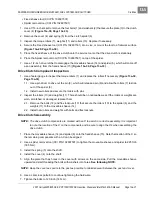
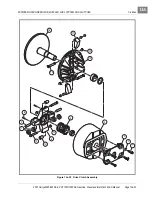
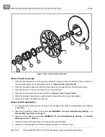
1. Use a 7/16-inch socket to remove the four bolts (1) and washers (2) that secure the plate (3) to the clutch
cover (4)
(Figure 13a-30, Page 13a-33)
.
2. Remove the cover (4) and spring (5) from the clutch spider (6).
3. Inspect the torque rollers (7), weights (11) and rollers (10). Replace if necessary.
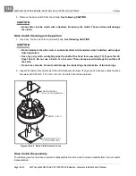
4. Secure the Fixed sheave tool (CCI P/N 102601501) into a vise, or mount the tool to a flat work surface
(Figure 13a-29, Page 13a-30)
.
5. Place the fixed sheave of the drive clutch onto the service tool so that the drive clutch is stationary.
6. Place the Spider removal tool (CCI P/N 102607501) on top of the spider.
7. Use a 1/2-inch drive ratchet to disengage the moveable sheave (14) and spider (6), which will come off
as an assembly, from the fixed sheave (15)
(Figure 13a-30, Page 13a-33)
.
Drive Clutch Component Inspection
1. Use a feeler gauge to inspect the torque rollers (7) and replace the rollers if necessary
(Figure 13a-30,
Page 13a-33)
.
1.1. Use a pin driver to drive out the pin (8), which will release a pin (9) and allow the rollers (7) to slide
out of the spider (6).
1.2. Install new rollers and secure the rollers with pins.
2. Inspect the rollers (10) and weights (11). There should be no noticeable wear. If the rollers or weights are
worn, scratched, or damaged, replace them.
2.1. Remove the bolts (12) and flex locknuts (13) that secure the rollers (10) to the spider (6) and the
weights (11) to the moveable sheave (14).
2.2. Install new rollers and weights with bolts and flex locknuts.
Drive Clutch Assembly
NOTE:
The drive clutch components are marked with an X to assist in correct reassembly. It is important
to note the location of the X on the components and be sure to align the X’s when assembling the
drive clutch.
1. Place the moveable sheave (14) and spider (6) onto the fixed sheave (15). Note the location of the X so
the remaining components with an X can be aligned.
2. Use a spider removal tool (CCI P/N 102607501) to tighten the moveable sheave and spider to 225 ft-lb
(305 N·m).
3. Install the spring (5) onto the shaft.
4. Install the cover (4) onto the shaft.
5. Align the plate that has holes in the cover with arrows on the same side. Pull the moveable sheave
upward and start threading the bolts with washers into holes.
See following NOTE.
NOTE:
Keep the cover as square to the post as possible to minimize wear between the post and cover.
6. Use a crisscross pattern to continue tightening the hardware.
7. Tighten the bolts to 120 in-lb (14 N·m).
Summary of Contents for IntelliTach XRT 1550
Page 2: ......
Page 22: ...1...
Page 54: ...4...
Page 60: ...5...
Page 90: ...6...
Page 114: ...8...
Page 118: ...9...
Page 196: ...11A...
Page 290: ...11C...
Page 468: ...13C...
Page 490: ...14...
Page 498: ...15...
Page 548: ...16...
Page 560: ...Club Car R NOTES...
Page 561: ...Club Car R NOTES...
Page 562: ...Club Car R NOTES...
Page 563: ......

