HYDRAULIC AND PARK BRAKE SYSTEMS
Brake Disc and Hub
2007 Carryall 295/295 SE & XRT 1550/1550 SE Gasoline, Diesel and IntelliTach M & S Manual
Page 6-15
6
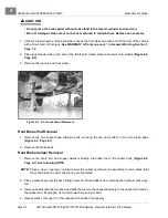
5. Secure the upright, wheel, and bearing assembly to the upper ball joint. Use a new nylon locknut and
tighten the hardware to 18 ft-lb (24 N·m).
6. Secure the upright, wheel, and bearing assembly to the lower ball joint. Use a new nylon locknut and
tighten the hardware to 18 ft-lb (24 N·m).
7. Secure the outer tie rod end to the upright arm. Use a new nylon locknut and tighten the hardware to 70
ft-lb (95 N·m).
8. Inspect the brake pads for wear and replace if necessary.
See Brake Disc and Pad Inspection on
page 6-3.
See Front Brake Pad Removal on page 6-6.
NOTE:
If brake pads are replaced on one side, replace the opposite side also.
9. Install the brake caliper on the upright.
See Front Brake Caliper Installation on page 6-7.
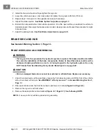
10. Install the hardened washer and new flanged spindle nut. Tighten, but do not torque the hardware to its
finished value.
11. Install the tire and wheel and finger-tighten the lug nuts.
12. Remove the jack stand. With the tires on the ground, use a crisscross pattern to tighten the lug nuts to
85 ft-lb (115 N·m).
13. Tighten the flanged spindle nut to 150 ft-lb (203 N·m).
14. Inspect the brake systems.
See Brake System Inspection on page 6-1.
REAR WHEEL DISC REMOVAL
ý
WARNING
• If at any point in this procedure the hydraulic system is opened, the brakes must be bled after
the correct reinstallation of the brake components. Failure to bleed the brakes could result in
decreased braking performance due to air being trapped in the hydraulic system. Use only
DOT 5 brake fluid. See Bleeding the Hydraulic Brake System on page 6-22.
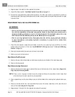
1. Chock the front wheels, release the park brake, and loosen the rear wheel lug nuts.
2. Remove the rubber dust cap.
3. Remove and discard the cotter pin.
4. Loosen and discard the castle nut on the axle spindle.
5. Lift the rear of the vehicle with a chain hoist or floor jack.
See WARNING “Lift only one end...” in Gen-
eral Warning, Section 1, Page 1-2.
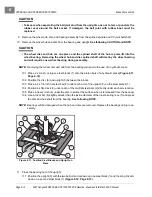
6. Place jack stands under the frame and lower it onto the stands
(Figure 6-16, Page 6-16)
.
7. Remove the lug nuts and wheel.
8. Remove the rear caliper from the axle tube. Secure the rear caliper to the respective swing arm assembly
with wire ties to remove pressure from the fittings and brake line.
9. Slide the splined wheel disc and hub from the axle spindle
(Figure 6-17, Page 6-16)
.
See following
NOTE.
Summary of Contents for IntelliTach XRT 1550
Page 2: ......
Page 22: ...1...
Page 54: ...4...
Page 60: ...5...
Page 90: ...6...
Page 114: ...8...
Page 118: ...9...
Page 196: ...11A...
Page 290: ...11C...
Page 468: ...13C...
Page 490: ...14...
Page 498: ...15...
Page 548: ...16...
Page 560: ...Club Car R NOTES...
Page 561: ...Club Car R NOTES...
Page 562: ...Club Car R NOTES...
Page 563: ......

