STEERING AND FRONT SUSPENSION
Front Suspension Components
2007 Carryall 295/295 SE & XRT 1550/1550 SE Gasoline, Diesel and IntelliTach M & S Manual
Page 7-13
7
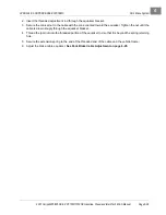
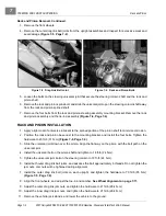
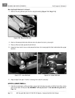
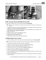
2. Insert the cam tool (CCI P/N 102447101) into the adjustment slot on the lower A-arm assembly.
3. Rotate the cam tool to adjust the bar until the desired dimension is achieved and the camber position is
positive.
4. Tighten the camber adjustment bar bolts to 53 ft-lb (72 N·m).
5. Check the measurement on the camber, and repeat steps 1 through 4 if necessary.
6. Repeat steps 1 through 5 for the remaining front wheel.
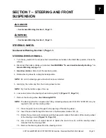
FRONT SUSPENSION COMPONENTS
See General Warning, Section 1, Page 1-1.
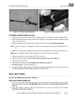
STEERING UPRIGHT REMOVAL
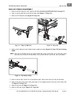
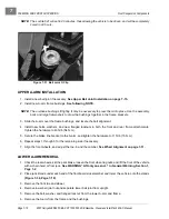
1. Chock the rear wheels, set the park brake, loosen the front wheel lug nuts, and lift the front of the vehicle
with a chain hoist or floor jack.
See WARNING “Lift only one end...” in General Warning, Section 1,
Page 1-2
.
2. Loosen the front wheel spindle nut.
3. Place jack stands under the outer front frame beams, and lower the vehicle onto the stands.
See Figure 6-2, Section 6, Page 6-6.
4. Remove the front tire and wheel.
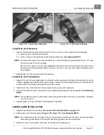
5. Remove the front brake caliper.
See Front Brake Pad and Caliper Removal, Section 6, Page 6-5.
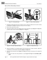
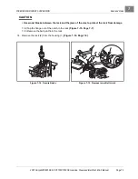
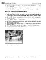
6. Rest the brake caliper on the A-arm. Ensure that there is no strain on the brake hose.
See following
WARNING.
ý
WARNING
• Strain on the brake hose or the brake hose fittings can result in damage to the line or fittings
and cause a leak in the hydraulic system, diminished brake performance, or brake failure.
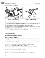
Figure 7-24 Measure Camber
Figure 7-25 Adjust Camber
B
A
Summary of Contents for IntelliTach XRT 1550
Page 2: ......
Page 22: ...1...
Page 54: ...4...
Page 60: ...5...
Page 90: ...6...
Page 114: ...8...
Page 118: ...9...
Page 196: ...11A...
Page 290: ...11C...
Page 468: ...13C...
Page 490: ...14...
Page 498: ...15...
Page 548: ...16...
Page 560: ...Club Car R NOTES...
Page 561: ...Club Car R NOTES...
Page 562: ...Club Car R NOTES...
Page 563: ......

