HYDRAULIC AND PARK BRAKE SYSTEMS
Hydraulic Line Replacement
Page 6-18
2007 Carryall 295/295 SE & XRT 1550/1550 SE Gasoline, Diesel and IntelliTach M & S Manual
6
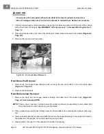
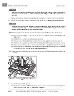
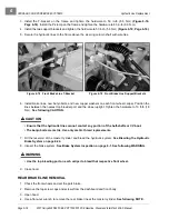
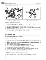
3. Install the T-bracket on the frame and tighten the hardware to 50 in-lb (5.6 N·m)
(Figure 6-18,
Page 6-18)
. Install the P-clamp on the frame and tighten the hardware to 85 in-lb (9.6 N·m).
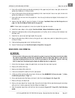
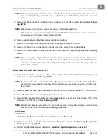
4. Install the two support brackets and tighten the hardware to 50 in-lb (5.6 N·m)
(Figure 6-19, Page 6-18)
.
5. Secure the hydraulic lines to the frame above the steering column shaft with wire ties.
6. Install brake lines, new banjo bolts, and new copper washers on each front wheel caliper. Position the
lines between the nearest top bleeder port and the wheel upright. Tighten the hardware to 13 ft-lb (18
N·m).
See following CAUTION.
ý
CAUTION
• Ensure that the hydraulic lines cannot contact any portion of the half-shafts or CV boot.
• The banjo bolts are metric. Use only metric thread replacements.
7. Fill the reservoir of the master cylinder and bleed the hydraulic system.
See Bleeding the Hydraulic
Brake System on page 6-22.
8. Inspect the brake system.
See Brake System Inspection on page 6-1.
See following WARNING.
ý
WARNING
• Use the top bleeding port on each caliper to bleed that respective front wheel.
9. Close hood.
REAR BRAKE LINE REMOVAL
1. Chock the front wheels and set the park brake.
2. Remove the top screw caps and screws from the dashboard and front body.
3. Open hood.
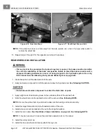
4. Use a flare-nut wrench to remove the rear brake line at the master cylinder.
See following NOTE.
Figure 6-18 Front Brake Line T-Bracket
Figure 6-19 Front Brake Line Support Brackets
Summary of Contents for IntelliTach XRT 1550
Page 2: ......
Page 22: ...1...
Page 54: ...4...
Page 60: ...5...
Page 90: ...6...
Page 114: ...8...
Page 118: ...9...
Page 196: ...11A...
Page 290: ...11C...
Page 468: ...13C...
Page 490: ...14...
Page 498: ...15...
Page 548: ...16...
Page 560: ...Club Car R NOTES...
Page 561: ...Club Car R NOTES...
Page 562: ...Club Car R NOTES...
Page 563: ......


