KAWASAKI GASOLINE ENGINE, MUFFLER, FUEL SYSTEM, AND CLUTCHES
Clutches
Page 13a-36
2007 Carryall 295/295 SE & XRT 1550/1550 SE Gasoline, Diesel and IntelliTach M & S Manual
13A
Driven Clutch Assembly
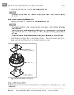
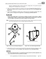
1. Place the fixed sheave (5) onto the spring compression base and note the location of the X so the X on
the moveable sheave (4) can be aligned correctly
(Figure 13a-32, Page 13a-36)
.
2. Place the moveable sheave (4) onto the fixed sheave (5) and align the X’s on both components.
3. Place the spring (3), cup (2), and snap ring (1) onto the clutch.
4. Place the spring compression collar onto the cup
(Figure 13a-31, Page 13a-35)
.
5. Tighten the spring compression nut just enough to enable the snap ring to be installed.
6. Use snap ring pliers to install the snap ring.
Driven Clutch Installation
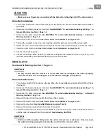
1. Turn the key switch OFF and remove the key. Set the park brake. Place the Forward/Reverse handle is
in NEUTRAL.
2. Disconnect the battery cables as instructed.
See WARNING “To avoid unintentionally starting...” in
General Warning, Section 1, Page 1-2.
3. Disconnect the spark plug wires.
See WARNING “To avoid unintentionally starting...” in General
Warning, Section 1, Page 1-2.
4. Install the driven clutch assembly on the transmission splined shaft.
5. Install the mounting washer and retaining bolt and tighten to 39 ft-lb (53 N·m).
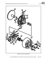
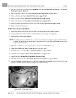
Figure 13a-32 Driven Clutch Assembly
1
2
4
5
3
6
6
"X"
"X"
Summary of Contents for IntelliTach XRT 1550
Page 2: ......
Page 22: ...1...
Page 54: ...4...
Page 60: ...5...
Page 90: ...6...
Page 114: ...8...
Page 118: ...9...
Page 196: ...11A...
Page 290: ...11C...
Page 468: ...13C...
Page 490: ...14...
Page 498: ...15...
Page 548: ...16...
Page 560: ...Club Car R NOTES...
Page 561: ...Club Car R NOTES...
Page 562: ...Club Car R NOTES...
Page 563: ......

