ELECTRICAL COMPONENTS: KAWASAKI POWERED GASOLINE VEHICLES
Fuel Level Sending Unit
Page 12a-14
2007 Carryall 295/295 SE & XRT 1550/1550 SE Gasoline, Diesel and IntelliTach M & S Manual
12A
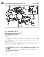
Front Differential Limit Switch Installation
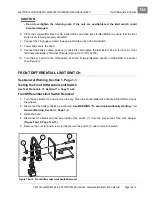
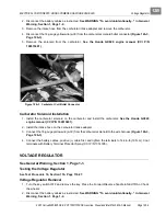
1. Install the front differential limit switch (1) in the reverse order of removal and tighten the nuts (2) to 4 in-
lb (0.5 N·m)
(Figure 12a-10, Page 12a-13)
.
See following CAUTION.
CAUT ION
• Do not overtighten the retaining nuts. If the nuts are overtightened, the switch could become
damaged.
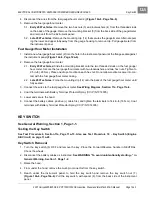
2. Move the accelerator pedal back and forth to ensure that the switch lever is being properly activated.
3. Connect the black and red wire leads of the switch to the gray wires of the wire harness.
4. Lower and secure the hood.
5. Connect the battery cables, positive (+) cable first, and tighten the terminals to 144 in-lb (16 N·m). Coat
terminals with Battery Terminal Protector Spray (CCI P/N 1014305).
FUEL LEVEL SENDING UNIT
See General Warning, Section 1, Page 1-1.
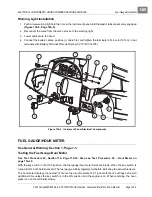
Thoroughly test the fuel level sending unit before replacing the unit.
Testing the Fuel Level Sending Unit
See Test Procedure 24, Section 11a, Page 11a-32.
Fuel Level Sending Unit Removal
See Fuel Level Sending Unit Removal, Section 13a, Page 13a-11.
Fuel Level Sending Unit Installation
See Fuel Level Sending Unit Installation, Section 13a, Page 13a-12.
IGNITION COIL AND CHARGE COIL
See General Warning, Section 1, Page 1-1.
It is recommended that the ignition coil and charge coil be thoroughly tested prior to replacement.
Testing the Ignition Coil
See Test Procedure 15, Section 11a, Page 11a-26. See also Test Procedure 16 – Engine Kill Wire on
page 11a-27, Test Procedure 17 – Grounded Kill Wire on page 11a-28. For charge coil testing, see Test
Procedure 13 – Charge Coil on page 11a-25.
Ignition Coil and/or Charge Coil Removal
The ignition coils are located under the flywheel shroud of the engine and the charge coil is located behind the
flywheel. Replacement requires the removal and installation of the engine. It is recommended to thoroughly
test the coils prior to replacement.
See Engine Removal on page 13a-1.
Refer to the engine manual for additional testing, removal, disassembly, and installation procedures.
See the Kawasaki FH680D engine manual (CCI P/N 103351201).
Summary of Contents for IntelliTach XRT 1550
Page 2: ......
Page 22: ...1...
Page 54: ...4...
Page 60: ...5...
Page 90: ...6...
Page 114: ...8...
Page 118: ...9...
Page 196: ...11A...
Page 290: ...11C...
Page 468: ...13C...
Page 490: ...14...
Page 498: ...15...
Page 548: ...16...
Page 560: ...Club Car R NOTES...
Page 561: ...Club Car R NOTES...
Page 562: ...Club Car R NOTES...
Page 563: ......


