Installation
FQ2-S/CH User’s Manual
43
2
Install
ation an
d
C
onn
ecti
ons
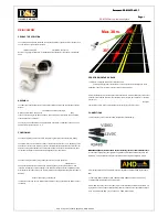
The X axis in the above optical diagrams represent field of view (mm)
*1
.
The Y axis represents the camera installation distance (mm) or WD (mm). These optical diagrams show the
relationship between the detection range and installation distance for different CCTV Lenses.
The values vary for each Lens.
Pay close attention to the Lens that you are using when you refer to these optical diagrams.
The macro ring thickness to be used is given as, for example “t5.0,” on the graphs. “t0” means that a macro
ring is not required. “t5.0” means that you must use a 5-mm macro ring.
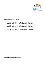
Lens Models and Dimensions
Field of view
Y
X
*1: The Y axis in the optical charts represents the height of the field of view.
*1: The Y axis in the optical charts represents the height of the field of view.
Extension t
@
(mm)
Camera
Camera lens
Measurement object
Camera installation distance (mm)
Field of view (mm)
Example: If you use an 3Z4S-LE SV-2514H Lens for a measurement object that requires field of view of 35
mm, the camera installation distance must be 200 mm and a 2-mm macro ring is required.
Filter threads
1-32 UNF
(C-mount threads)
Maximum outside
diameter
Total length
Summary of Contents for FQ2-S/CH Series
Page 1: ...User s Manual Smart Camera FQ2 S CH Series Cat No Z337 E1 06...
Page 12: ...10 FQ2 S CH User s Manual MEMO...
Page 74: ...Setting Up Ethernet 72 FQ2 S CH User s Manual MEMO...
Page 366: ...Editing the Model Region Measurement Region from Run Mode 364 FQ2 S CH User s Manual MEMO...
Page 432: ...Functions Related to the System 430 FQ2 S CH User s Manual MEMO...
Page 587: ...Index FQ2 S CH User s Manual 585 Index 9...
Page 589: ......