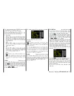
Base menu - Control/switch setting
Control and switch assignment
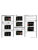
In the basic transmitter display, use your finger or the
provided stylus to touch the gear icon labeled "B":
Touch
The display switches to the "green" base menu. Touch
the menu item
"
TX Ctl
".
Touch
Near the gimbal sticks for the control functions 1 ...
4 and their trim controls the
mz-24
HoTT Pro trans-
mitter is provided as standard with other control ele-
ments:
• 1 two-position switch with long handle (S6)
• 1 three-position switch with long handle (S3)
• 4 three-position switches with a short handle (S1,
S4, S5 and S7)
• 2 one-side, self-neutralizing three-position switch-
es with long handle (S2 and S8)
• 2 INC/DEC buttons (DT1 and DT2)
• 2 rear proportional sliders (SL1 and SL2)
• 4 proportional dials (DV1 … DV4)
In contrast to the two control sticks that immediately
act on the servos connected to receiver outputs 1 ... 4
with a newly initialized model memory and for an heli-
copter model also for the servo 6, the aforementioned
control elements are initially inactive.
Consequently, only the servos controlled by the two
control sticks can be moved when these systems are
initially delivered and a new model memory is initial-
ized and bound to the receiver to be installed. In con-
trast, the servos connected to different slots remain in
their middle position.
Even though this may initially appear to be inconve-
nient ..., it is the only way to freely select from the
"other" control elements of your transmitter and avoid
the deactivation of unnecessary control elements. A
not needed control element, erroneously actioned,
also has then no influence on your model if it is not ac-
tive, it means when it is not assigned to any function.
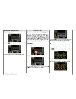
As needed, you can therefore assign all of the afore-
mentioned control elements within the "
CTL Set
"
sub-menu addressed here to any function input with-
out restriction, . This also means that each of these
control elements can also be simultaneously assigned
several functions as needed. For example, the same
toggle switch that is assigned to an input in this menu
can also be assigned as a timer on/off switch in the
"
Timer
" menu, etc.
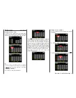
Notices
• It should be noted that incorrect responses
may arise from functional overlaps such as
using the same physical switch as a switch
to switch between Phase switch and as a
control for Phase trimming. Change also your
switch assignment.
• In contrast to setting servo travel, setting the
control travel affects
all outgoing
mixing and
coupling functions and hence all servos that
are activated by the relevant control element.
•
The control direction of the brake
control of a "glider model", generally
the "front" position of the CH1 control
stick, is defines through the off-set value in the
line "CTL OFFSET" of the "
BUTTERFLY
" sub-
menu.
The conversion of the control direc-
tion of the throttle control stick (CH1)
of a motor powered model is de-
scribed in the sub-menu "
Throttle CURVE
"
context.
The conversion of the control direc-
tion of the throttle/pitch control stick
(CH1) of a helicopter model is de-
scribed in the sub-menu "
Pitch curve
" con-
text.
The conversion of
the control direction
of the throttle control
stick (CH1) of these three model types is de-
scribed in the sub-menu "
Throttle CURVE
"
context.
90
Base menu - Control/switch setting
Summary of Contents for mz-24 PRO
Page 13: ...13 Personal notes...
Page 19: ...19 Personal notes...
Page 37: ...37 Personal notes...
Page 59: ...Touch 59 Base menu Model selection...
Page 79: ...79 Personal notes...
Page 89: ...89 Personal notes...
Page 115: ...115 Personal notes...
Page 153: ...Helicopter model function menus Common function menus 153 Personal notes...
Page 169: ...169 Personal notes...
Page 187: ...187 Personal notes...
Page 199: ...199 Personal notes...
Page 207: ...Fixed wing model function menus System menus 207 Personal notes...
Page 211: ...211 Personal notes...
Page 219: ...219 Personal notes...
Page 237: ...237 Personal notes...
Page 238: ...238 Personal notes...
Page 239: ...239 Personal notes...


