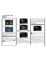
Since the throttle curve in this case only determines
the target speed of the motor control unit and this
target speed normally remains constant over the en-
tire pitch adjustment range, set a horizontal line in the
"Throttle curve" sub-menu (each (pitch) input value
results in the same (throttle) output value) whose level
determines the target speed.
First, delete support points 1 to 5 that may be set, and
then set the support points "L" (input = 0%) and "H"
(input = +100%) to the
same
value, for example:
The value to be set depends on the governor that is
used as well as the desired target speed, and can of
course be varied for specific phases.
Tip
If required the implemented governor function can be
phase specifically trimmed after the required program-
ming of a free mixer by tapping on one of the two di-
gi-trim buttons of the
mz-24
HoTT Pro transmitter with-
in a maximum of ±37,5 %, see
Programming example
.
This options offers you the possibility to correct the trim-
ming of the phase specific (and at any time recallable)
governor through only one control element.
Notice
If, as previously described, the throttle curve is
used to control a
governor
, all the mixers of the
"
THR.MIX
" menu have to be left on
INH
.
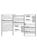
Adjusting the throttle and pitch curve
The throttle and pitch control are always activated by
separate servos which, however, are always activated
together by the throttle/pitch control stick (except in
the autorotation phase). The helicopter program auto-
matically couples the servos. The trim lever for control
function 1 in principle only acts on the throttle servo of
the
mz-24
HoTT Pro transmitter programs.
The coordination of throttle and pitch, i.e., the perfor-
mance curve of the motor with collective blade ad-
justment, is the most important setting for helicopters.
The
mz-24
HoTT Pro transmitter programs allow the
throttle, pitch and torque compensating curves to be
independently adjusted.
These curves can be characterized with up to sev-
en points, but generally fewer points are sufficient.
It is strongly recommended to first start with 3-point
curves. Individual values can be entered for the cen-
ter position and any other support points, as well as
for the two end positions ("L" ("low") and "H" ("high"))
of the throttle/pitch control stick which establish the
control curves.
Before adjusting the throttle and pitch function, the
linkage of all servos must be first correctly pre-adjust-
ed mechanically according to the helicopter's adjust-
ing instructions.
Notice
The hovering point should always be in the center
position of the throttle/pitch control stick. In spe-
cial cases, for example for 3-D flight, deviating
hovering points can also be programmed, for example a
point for the normal flight position above the center, and
a point for inverted flight below the center.
Idle setting and throttle curve
Notice
Since electric drives do not require an idle setting,
an idle adjustment is unnecessary with this type
of drive. The coordination of the throttle and
pitch curve(s) described here is similar to gas helicop-
ters, however.
The
Idle setting
, is done exclusively when the throttle
limiter is closed, normally with the trim control of the
CH1 function, and only in special cases with the throt-
tle limiter as well.
Programming a corresponding value at the "L" point
of the throttle curve adjusts the descent speed of the
motor without influencing the hovering setting.
You can use the phase programming, for example, to
set different throttle curves. This higher system speed
below the hovering point is useful for example in fast,
steep landing approaches when the pitch is very low,
and in aerobatics.
The figure shows a curve with a
throttle position that changes slightly
below the hovering point in the control
center.
162
Function menu | Helicopter model - Throttle curve
Summary of Contents for mz-24 PRO
Page 13: ...13 Personal notes...
Page 19: ...19 Personal notes...
Page 37: ...37 Personal notes...
Page 59: ...Touch 59 Base menu Model selection...
Page 79: ...79 Personal notes...
Page 89: ...89 Personal notes...
Page 115: ...115 Personal notes...
Page 153: ...Helicopter model function menus Common function menus 153 Personal notes...
Page 169: ...169 Personal notes...
Page 187: ...187 Personal notes...
Page 199: ...199 Personal notes...
Page 207: ...Fixed wing model function menus System menus 207 Personal notes...
Page 211: ...211 Personal notes...
Page 219: ...219 Personal notes...
Page 237: ...237 Personal notes...
Page 238: ...238 Personal notes...
Page 239: ...239 Personal notes...


