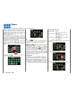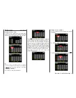
In the basic transmitter display, use your finger or the
provided stylus to touch the gear icon labeled "B":
Touch
The display switches to the "green" base menu. Touch
the menu item "
Servo
".
Touch
The optical display of the actual servo positions can
be recalled at any time not only through the previously
described selection of this menu item but alternatively
by inactive value fields
also from the basic display and
from almost all the menu positions by pushing at the
same time the
buttons on the left of the display.
Pushing the
ESC
button, which is directly underneath,
brings you back to the originally menu point.
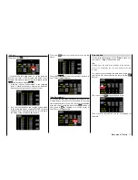
Phase depending displays
The here mentioned sub-menu offers the possibility
to display phase specific values. Recognizable on the
top left side of the display in green color is displayed
the phase name. As standard is displayed the name
of the phase 1, which is indicated by the name "NOR-
MAL" or "PHASE 1".
As soon as you will have defined one or many oth-
er phases in the "
PHASE
" menu, you will be able to
switch among those phases. Activate the correspond-
ing switch or switches if desired to switch between
the phases.
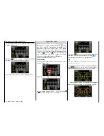
Servo monitor
The current setting of each servo is displayed precise-
ly between -150% and +150% of the normal path tak-
ing into account the control and servo settings, dual
rate/expo functions, the interaction between the linear
and curve mixes, etc. 0% equals the middle position
of the servo. You can therefore quickly check your
settings without having to turn on the receiver. This
does not relieve you of the responsibility, however, of
carefully testing all the program steps on the model
before first use to make sure there are no errors.
The display follows the assignment below for:
Land and water models
Please refer to your channel assignation.
Copter
Bar 1
Pitch (climb/sink)
Bar 2
Roll
Bar 3
Nick
Bar 4
Yaw
Bar 5 ... 12
related to your assignation
Helicopter models
Bar 1
Pitch or roll (2) or nick (2) servo
Bar 2
Roll (1) servo
Bar 3
Nick (1) servo
Bar 4
Yaw servo (gyro)
Bar 5
Nick (2)-Servo / free channel
Bar 6
Throttle servo or governor
Bar 7
Gyro sensitivity / free channel
Bar 8
Speed controller / free channel
Bar 9
Free channel
Bar 10
Free channel
Bar 11
Free channel
Bar 12
Free channel
Fixed-wing models
Bar 1
Throttle/brake servo
Bar 2
Aileron or left aileron
Bar 3
Elevator
Bar 4
Rudder
Bar 5
Aileron right
Bar 6
Flap (left) / free channel
Bar 7
Flap (right) / free channel
Bar 8
Free channel / second elevator servo
Bar 9
Free channel / AILE2 left
Bar 10
Free channel / flap2 right
Bar 11
Free channel / AILE2 left
Bar 12
Free channel / AILE2 right
Notices
• Because for the model types "Car", "Copter"
and "Boat" there is no established pre-assig-
nation, for those model types it is not possible
to offer a reference list of assignation.
• Note that the servo display refers exclusively
to the original sequence of the servos, that is,
it does not refer to any changes to the out-
Servo monitor
Display of servo positions and servo test function
86
Base menu - Servo monitor
Summary of Contents for mz-24 PRO
Page 13: ...13 Personal notes...
Page 19: ...19 Personal notes...
Page 37: ...37 Personal notes...
Page 59: ...Touch 59 Base menu Model selection...
Page 79: ...79 Personal notes...
Page 89: ...89 Personal notes...
Page 115: ...115 Personal notes...
Page 153: ...Helicopter model function menus Common function menus 153 Personal notes...
Page 169: ...169 Personal notes...
Page 187: ...187 Personal notes...
Page 199: ...199 Personal notes...
Page 207: ...Fixed wing model function menus System menus 207 Personal notes...
Page 211: ...211 Personal notes...
Page 219: ...219 Personal notes...
Page 237: ...237 Personal notes...
Page 238: ...238 Personal notes...
Page 239: ...239 Personal notes...


