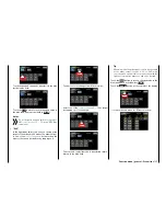
… and assign a switch or control switch as described
in section
Control and switch assignment
:
After you have finished making your settings, touch
the
BACK
button at the top left of the display to return
to the mixer selection:
Setting curve mixers 6 … 8
These three curve mixers make it possible to define
extremely nonlinear mixer guide lines with up to five
freely positionable points between the two endpoints
"L" (low = -100% control travel) and "H" (high =
+100% control travel) along the control travel.
Programming details
The control curve is defined by up to 7 points, so-
called support points. In the default settings of the
program, 2 support points are already defined, the
endpoints "L" and "H".
Notice
The following examples are only for demonstra-
tion purposes and do not represent a realistic
mixer guide line.
Setting support points
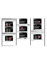
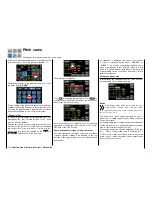
A green vertical line (normally hidden) is moved syn-
chronously in the graphic between the two endpoints
with the mixer input control, here the control function
8 of the side proportional rotary control SL1.
To show this line, touch the
ST OFF
button at the
bottom left:
Touch
After this value field is switched to
ST ON
, the green
vertical line representing the momentary control posi-
tion appears, and the control position is also numeri-
cally displayed in the "IN(put)"line.
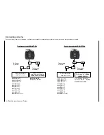
In the following example, the control at input 8 is at
-45% of the control travel. The output signal remains
0% since a value has not been entered:
The intersection of this line with the mixer curve is
identified as "OUT(put)" and can be varied at the sup-
port points within a range of ± 125% (see below). This
resulting control signal affects the mixer output.
Between
the two endpoints "L" and "H", up to five
additional support points can be set, and the distance
between neighboring support points may not be less
than approximately 25%.
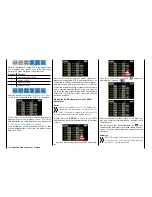
Move the green line through the related control. As
soon as you tap on
ENT
, right on the bottom …
Touch
… a red dot appears at the interface between the
two lines. At the same time, the "?" is replaced with
a point number, and the value field to the right shows
the current output value:
As described below, the set point can be moved hor-
izontally with the
X-axis
function within a range of
approximately ± 90%, and vertically with the
Y-axis
function within a range of ±125%.
Notice
If the relevant control is not set precisely at the
support point, it should be remembered that the
percentages of the "input" and "output" lines al-
ways refer to the momentary control position.
Use the same procedure for the other support points.
The sequence in which the up to five points between
the end points "L" and "H" are generated does not
matter since the support points are automatically re-
numbered sequentially from left to right after one sup-
port point is set or deleted.
139
Function menu | general - Free mixer
Summary of Contents for mz-24 PRO
Page 13: ...13 Personal notes...
Page 19: ...19 Personal notes...
Page 37: ...37 Personal notes...
Page 59: ...Touch 59 Base menu Model selection...
Page 79: ...79 Personal notes...
Page 89: ...89 Personal notes...
Page 115: ...115 Personal notes...
Page 153: ...Helicopter model function menus Common function menus 153 Personal notes...
Page 169: ...169 Personal notes...
Page 187: ...187 Personal notes...
Page 199: ...199 Personal notes...
Page 207: ...Fixed wing model function menus System menus 207 Personal notes...
Page 211: ...211 Personal notes...
Page 219: ...219 Personal notes...
Page 237: ...237 Personal notes...
Page 238: ...238 Personal notes...
Page 239: ...239 Personal notes...


