Notice
The associated controller does not have any
effect if an undefined point is selected (in the
basic version of the relevant curve mixers,
only the points "L" and "H" are set).
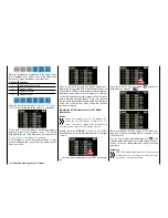
• "PHASE" column
If you want to, specify in the right "PHASE" column
the phase in which the governor should be active.
In the value field, in the example, "1 (normal)", the
number refers to the phase number that can be
found in the sub-menu "
PHASE
".
To select another phase than default Phase1,
touch the button in the "Phase" column in the de-
sired line, for example:
You can change the current Phase number in the
blue (active) value field by touching the
+
or
–
buttons at the right edge of the display the desired
number of times, for example:
Touch the
RES
button to reset a changed value in
a blue (active) value field to the default value.
Notice
When selecting a not defined phase, as stan-
dard only the Phase 1 is active, the associat-
ed controller does not have any effect.
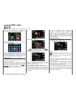
After you finish making your settings, touch the
BACK
button at the top left of the display to leave this menu
and go to "Pitch curve":
Touch
Notice
The settings that appear in this display affect the
same records as those at a comparable location
in the "TRIM" display of the "
THR.CRV
" sub-
menu , see next section, which is why changes al-
ways affect each other.
Autorotation setting
In a powered flight, the maximum wing angle is lim-
ited by the available motor output; in autorotation
flight, however, it is limited by the stall at the main
rotor blades. To provide sufficient lift even while the
speed is decreasing when flaring the helicopter, the
maximum pitch needs to be set.
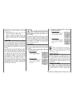
Switch to the autorotation phase, and move the green
vertical line to the "H" point with the control stick.
First set a value that is about 10 to 20%
higher
than
the normal maximum pitch. Do not set a value at the
very beginning that is significantly higher than normal
flight since of the behaviour of the pitch control will
be significantly different after switching in comparison
to the usual reaction. The danger exists of over-con-
trolling after flaring with the model continuing to rise;
then the motor speed will decrease suddenly high
above the ground, and the model will drop. Later, af-
ter a few test autorotations, the value can always be
readjusted.
The minimum pitch
can
be different from that for nor-
mal flight. It depends on conventional control practice
during normal flight. In any case, you need to set a
minimum pitch for the "L" point for autorotation that
will allow your model to be brought into a descent
of approximately 60-70° out of a forward flight path
at an average speed when the pitch is reduced to a
minimum. If you use such a setting in normal flight
like most of helicopter pilots, the value can be easily
transferred.
If you normally let your model descend at a flatter an-
gle, increase the value at the "L" point and vice versa.
158
Function menu | Helicopter model - Pitch curve
Summary of Contents for mz-24 PRO
Page 13: ...13 Personal notes...
Page 19: ...19 Personal notes...
Page 37: ...37 Personal notes...
Page 59: ...Touch 59 Base menu Model selection...
Page 79: ...79 Personal notes...
Page 89: ...89 Personal notes...
Page 115: ...115 Personal notes...
Page 153: ...Helicopter model function menus Common function menus 153 Personal notes...
Page 169: ...169 Personal notes...
Page 187: ...187 Personal notes...
Page 199: ...199 Personal notes...
Page 207: ...Fixed wing model function menus System menus 207 Personal notes...
Page 211: ...211 Personal notes...
Page 219: ...219 Personal notes...
Page 237: ...237 Personal notes...
Page 238: ...238 Personal notes...
Page 239: ...239 Personal notes...

