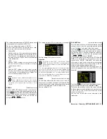
When the voltage falls below the set alarm thresh-
old, a warning tone sounds, and "
VOLT.E
" appears in
white at the top right in all "RX..." displays.
In the "RX DATAVIEW" display, the parameter
"
R-VOLT"
is displayed in white.
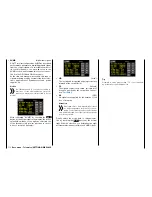
ALARM TEMP +/-
(receiver temperature monitoring)
These two options monitor the receiver temperature.
You can program a bottom threshold "ALARM TEMP-
" (-20 … +10°C) and an upper threshold "ALARM
TEMP+" (+50 … +80°C). If the upper or lower thresh-
olds are exceeded, a continuous warning tone
sounds, and "
TEMP.E
" appears in white at the top
right in all receiver displays. On the display page "RX
DATAVIEW", the parameter "
R-TEM"
is also displayed
in red or white.
Make sure that the temperature of your receiver re-
mains within the permissible range under all operating
conditions (ideally between -10 and +55°C).
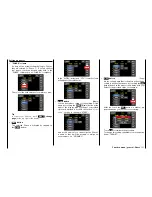
CH OUTPUT TYPE
(connection type)
In this line, select the type of servo control or alter-
nately the signal type of the aggregate signal output:
• ONCE
The servo connections of the receiver are actuat-
ed sequentially. Recommended for analog servos.
With this setting, the servos are automatically op-
erated at a cycle of 20 ms (30 ms for a 12 channel
GR-24 receiver (No.
33512
)) no matter what is set
or displayed in the "RX SERVO" display in the line
"PERIOD".
• SAME
The servo connections of the receiver are actuat-
ed simultaneously in blocks. That is, the servos
connected to connections 1 to 4 as well as 5 to
8 can be simultaneously supplied with their con-
trol signals with a GR-16 receiver (No.
33508
), and
the servos connected to connections 1 to 4, 5 to
8 as well as 9 to 12 can be simultaneously sup-
plied with their control signals with a GR-24 receiv-
er (No.
33512
).
This is recommended for digital servos when sev-
eral servos are used for a single function (such as
. an aileron) so that the servos are fully synchro-
nized.
When exclusively digital servos are used, it is rec-
ommendable to set "10 ms" in the line "PERIOD"
of the display "RX SERVO" to exploit the fast re-
action of digital servos. When analogue servos or
mixed operation is used, be sure to select "20 ms".
Attention
When this setting is used, make sure that the
receiver power supply is sufficiently large.
Since four servos are always triggered simul-
taneously when "SAME" is selected, the power sup-
ply is subjected to a related load.
• SUMO
(aggregate signal OUT)
A HoTT receiver configured as SUMO always gen-
erates an aggregate signal from the control signals
of all its controls channels, and forwards this to
servo connection 8 of the GR-16 (No.
33508
) and
GR-24 receiver (No.
33512
).
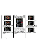
With receivers that have a two-digit number to the
right of "SUMO" in their display,...
… the active field switches to the right to chan-
nel selection by touching the
SET
button at the
bottom right after "SUMO" is confirmed. With the
selection, you determine the
highest
control chan-
nels within the SUMO signal.
110
Base menu - Telemetry | SETTINGS/DISPLAYS
Summary of Contents for mz-24 PRO
Page 13: ...13 Personal notes...
Page 19: ...19 Personal notes...
Page 37: ...37 Personal notes...
Page 59: ...Touch 59 Base menu Model selection...
Page 79: ...79 Personal notes...
Page 89: ...89 Personal notes...
Page 115: ...115 Personal notes...
Page 153: ...Helicopter model function menus Common function menus 153 Personal notes...
Page 169: ...169 Personal notes...
Page 187: ...187 Personal notes...
Page 199: ...199 Personal notes...
Page 207: ...Fixed wing model function menus System menus 207 Personal notes...
Page 211: ...211 Personal notes...
Page 219: ...219 Personal notes...
Page 237: ...237 Personal notes...
Page 238: ...238 Personal notes...
Page 239: ...239 Personal notes...


