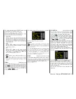
RX SERVO TEST
With the RX SERVO TEST function, you can test the
servos connected to the currently active receiver:
Value
Explanation
Possible set-
tings
Vx.xx
Firmware version
of the receiver
None
ALL-MAX
Servo travel on
the "+" side for all
servo outputs for
the servo test
1500 … 2000 µs
ALL-MIN
Servo travel on
the "-" side for all
servo outputs for
the servo test
1500 … 1000 µs
TEST
Test procedure
START / STOP
ALARM
VOLT
Alarm threshold
for the receiver’s
low voltage war-
ning
3.0 … 7.5 V
factory setting:
3.8 V
ALARM
TEMP+
Alarm threshold
when the receiver
temperature is too
high
50 … 80 °C
factory setting:
55 °C
ALARM
TEMP–
Alarm threshold
when the receiver
temperature is too
low
-20 … +10 °C
factory setting:
-10 °C
CH OUTPUT
TYPE
Channel sequen-
ce or type of agg-
regate symbol
ONCE, SAME,
SUMI, SUMO
and SUMD
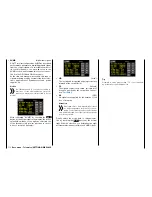
ALL-MAX
(servo travel on the "+" side)
In this line, set the maximum servo travel on the plus
side of the control travel for the servo test.
2000 μs corresponds to a full deflection on the "+"
side of the servo travel, and 1500 μs corresponds to
the neutral position.
Make sure that the servos do not strike anything
during the test routine.
ALL-MIN
(servo travel on the "+" side)
In this line, set the maximum servo travel on the minus
side of the control travel for the servo test.
1000 μs corresponds to a full deflection on the "-" side
of the servo travel, and 1500 μs corresponds to the
neutral position.
Make sure that the servos do not strike anything
during the test routine.
TEST
(start/stop)
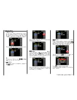
In this line, briefly touch the
SET
button at the bottom
right of the display to start and stop the servo test
integrated in the receiver.
Use the
INC
or
DEC
button to select "
START
"...
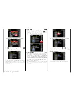
... and touch the
SET
button again at the bottom
right of the display to start the test. The entry field
returns to normal:
To stop the servo test, reactivate the entry field as de-
scribed above, select "
STOP
", and confirm by touch-
ing the
SET
button at the bottom right.
ALARM VOLT
(receiver low voltage warning)
Through the "ALARM VOLT" the operating voltage of
the receiver is monitored. The alarm threshold can be
set between 3,0 and 7,5 Volt in 0,1 Volt steps.
109
Base menu - Telemetry | SETTINGS/DISPLAYS
Summary of Contents for mz-24 PRO
Page 13: ...13 Personal notes...
Page 19: ...19 Personal notes...
Page 37: ...37 Personal notes...
Page 59: ...Touch 59 Base menu Model selection...
Page 79: ...79 Personal notes...
Page 89: ...89 Personal notes...
Page 115: ...115 Personal notes...
Page 153: ...Helicopter model function menus Common function menus 153 Personal notes...
Page 169: ...169 Personal notes...
Page 187: ...187 Personal notes...
Page 199: ...199 Personal notes...
Page 207: ...Fixed wing model function menus System menus 207 Personal notes...
Page 211: ...211 Personal notes...
Page 219: ...219 Personal notes...
Page 237: ...237 Personal notes...
Page 238: ...238 Personal notes...
Page 239: ...239 Personal notes...


