In the basic transmitter display, use your finger or the
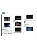
provided stylus to touch the gear icon labeled "S":
Touch
The display switches to the purple main menu. Touch
the menu item
"
Stick Cali
".
Touch
Touch
If you feel that the center position of your self-neutral-
izing control stick (controls 1 … 4) does not precisely
correspond to 0% control travel, you can check and
correct it as follows:
Initialize
a free model memory
. For which model type
you decide is completely irrelevant. It is only import-
ant that no trimming or programming has been per-
formed.
Stick calibration
Calibration of the neutral position of the two control sticks
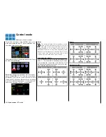
Change from that to the "
"Servo"
" sub-menu by tap-
ping at the same time the
on the left of the dis-
play.
If all four of your transmitter's control stick functions
are still self-neutralizing, this display should ideally
look like the one shown below.
Otherwise the graph bars show current setting per-
centages for control stick control functions which are
not self-neutralizing, normally CH1. For example, if
the CH1 control stick is in its "idle LOW" position, the
display would appear as shown below.
One after the other, put both control sticks into each
of their four possible limit positions
without
exerting
force at the limit position. In each of these eight pos-
sible limit positions, the – side dependent – indication
for exactly -100% or +100% should be displayed. For
example, if control 2 is at its right limit and the other
three other control stick functions are in their respec-
tive middle positions, then your transmitter's display
should look like the one shown below.
Regardless of the number of self-neutralizing control
stick functions available on your transmitter, if these
checks produce four 0% results and eight 100% re-
sults, then your transmitter's control sticks are opti-
mally calibrated. You can terminate this process and
then, if appropriate, delete the model memory just
created.
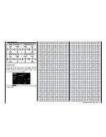
Otherwise, switch to the sub-menu "
Stick Cali
" of the
system menu in which you can cyclically selected the
positions of the four stick levers that can be calibrat-
ed, starting with the neutral position of the right con-
trol stick system:
The blue point (in the midpoint of the square in the
display above) indicates the stick position to be ad-
justed.
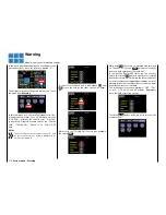
The percentages in white in the red rectangles on the
left of the display under VERTI(cal) and HORIZ(ontal)
indicate the current stick position.
Although the right-hand stick is located exactly in the
middle of its path due to its horizontal self-neutraliza-
tion, an example adjustment of +2% is shown in the
figure above.
220
System menu - Joystick calibration
Summary of Contents for mz-24 PRO
Page 13: ...13 Personal notes...
Page 19: ...19 Personal notes...
Page 37: ...37 Personal notes...
Page 59: ...Touch 59 Base menu Model selection...
Page 79: ...79 Personal notes...
Page 89: ...89 Personal notes...
Page 115: ...115 Personal notes...
Page 153: ...Helicopter model function menus Common function menus 153 Personal notes...
Page 169: ...169 Personal notes...
Page 187: ...187 Personal notes...
Page 199: ...199 Personal notes...
Page 207: ...Fixed wing model function menus System menus 207 Personal notes...
Page 211: ...211 Personal notes...
Page 219: ...219 Personal notes...
Page 237: ...237 Personal notes...
Page 238: ...238 Personal notes...
Page 239: ...239 Personal notes...

