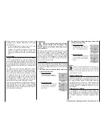
Swashplate limiter
Adjustable limitation and rotation of deflection
In the basic transmitter display, use your finger or the
provided stylus to touch the gear icon labeled "F":
Touch
The display switches to the blue function menu. Touch
the menu item "
S.Limit
":
Touch
Swashplate limiter
This function acts like a circular mechanical fence that
limits the normally square path ...
… of a control stick (marked with a red circle) to a
maximum of one circular area provided that the limiter
is turned
ON
in the "ACT" line:
If the helicopter is adjusted so that the deflections for
roll and/or elevation exploit the maximum travel me-
chanically possible, e. g. for 3D helicopters, then the
total tilt applied to the swashplate if full roll and ele-
vation commands are applied simultaneously will be
considerably greater (141% in numerical terms). The
swashplate mechanism may then strike its endstops
and, in the worst case, the ball-heads could even be
disengaged.
In the
mz-24
HoTT transmitter, the relevant software
function offers a limitation of the swashplate deflec-
tion that can be adjusted between any combination
of circular and square. That is, the limitation of the
overall swashplate deflection or the swashplate tilt
angle can be limited between 100% (the deflection
has a circular limit to the value achievable with roll or
elevation) and 200% (no effective limit) in the "SET"
line with the
+
or
–
buttons at the right edge of the
display. In addition, the function can be completely
deactivated by selecting
BLK
in the line "ACT".
Touch the
RES
button to reset a changed value in a
blue (active) value field to the default value.
Swash rotation
With some rotor head controls, it is necessary to tilt
the swashplate in another direction than the intended
rotor plane angle during cyclical control. For example
if a four-blade rotor is used, it may be necessary to
turn the actuation 45° to the right or left with this menu
item so that the control linkage from the swashplate
to the rotor head can be precisely vertical. This allows
the blades to be controlled correctly without undesir-
able differentiation. The controlling linkage then does
not have to be mechanically changed. Negative an-
gles equate to a virtual rotation of the rotor head to
the left; positive angles a virtual rotation to the right.
After making your settings, leave this menu and go to
"Menu selection" by touching the
BACK
button at the
top left of the display.
173
Function menu | Helicopter model - S. Limiter
Summary of Contents for mz-24 PRO
Page 13: ...13 Personal notes...
Page 19: ...19 Personal notes...
Page 37: ...37 Personal notes...
Page 59: ...Touch 59 Base menu Model selection...
Page 79: ...79 Personal notes...
Page 89: ...89 Personal notes...
Page 115: ...115 Personal notes...
Page 153: ...Helicopter model function menus Common function menus 153 Personal notes...
Page 169: ...169 Personal notes...
Page 187: ...187 Personal notes...
Page 199: ...199 Personal notes...
Page 207: ...Fixed wing model function menus System menus 207 Personal notes...
Page 211: ...211 Personal notes...
Page 219: ...219 Personal notes...
Page 237: ...237 Personal notes...
Page 238: ...238 Personal notes...
Page 239: ...239 Personal notes...


