Basic operating steps
•
ST OFF
/
ST ON
buttons
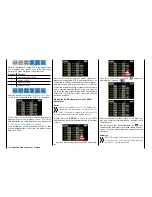
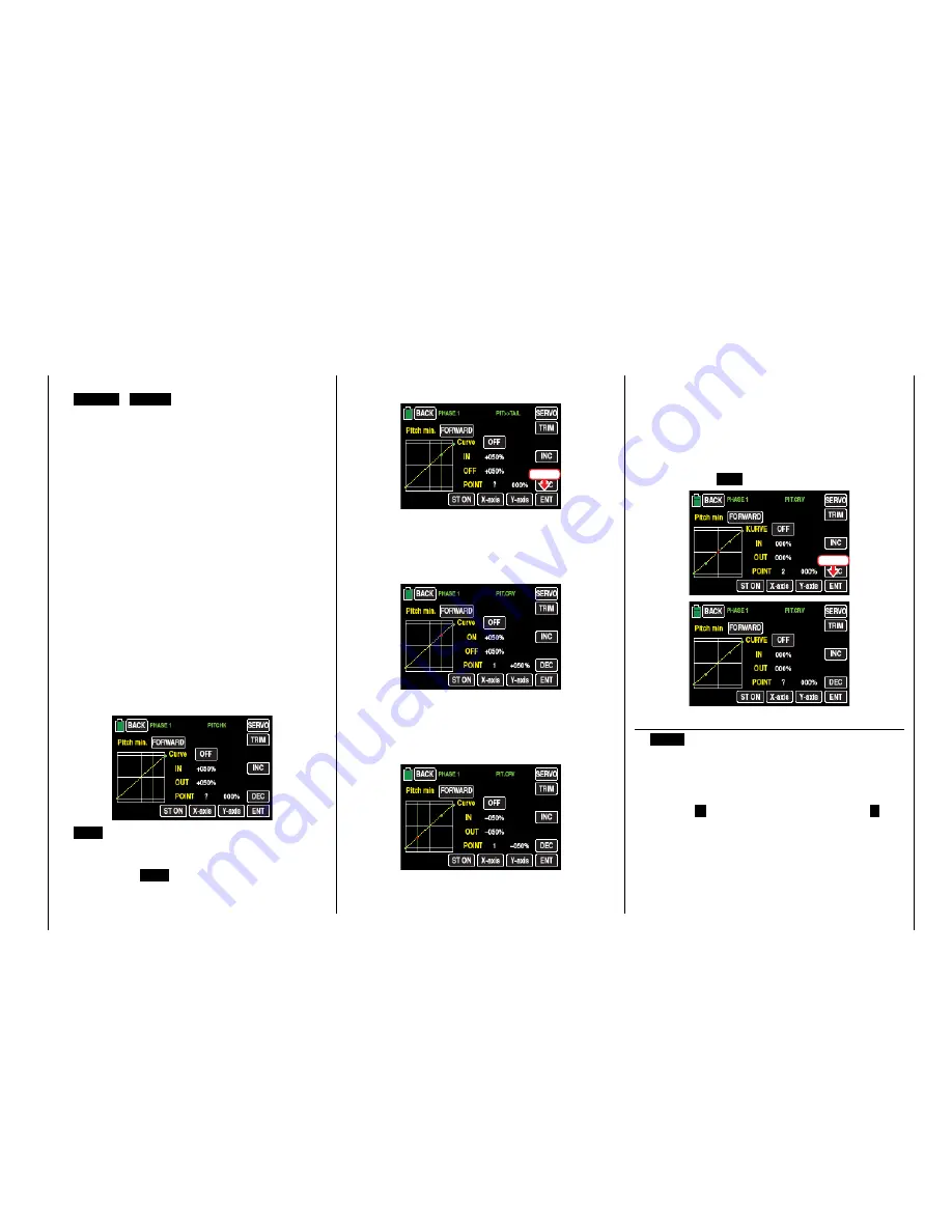
Touch this button to turn the graphic and numeric
display of the control stick position on or off.
In switch on stand through the control elements
(throttle/pitch control stick) a vertical green line is
moved synchronously in the graph between the
two endpoints "L" and "H". The momentary con-
trol stick position is also displayed numerically in
the line "IN"(put) (-100 % to +100 %). The inter-
section of this line with the curve is identified as
"OUT"(put) and can be varied at the support points
between -125% and +125%. The control signal
which is changed in this way then affects all of the
following mixing and coupling functions.
In the following example, the control stick is exact-
ly halfway between the middle and end of its path,
at +50% of the control path, and generates an out-
put signal that is also +50% due to the linear char-
acteristic.
Between
the two endpoints "L" and "H", up to 5
additional support points can be set, and the dis-
tance between neighboring support points may
not be less than approximately 25%.
•
ENT
button
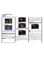
Move the control stick. As long as a "?" is next to
the "POINT", you can set the next support point by
touching the
ENT
button.
At the same time, a green point appears at the in-
tersection between the yellow and green lines:
Touch
Once the green line is moved with the control stick
around the point, it becomes red, the "?" is re-
placed with a number, and the point value appears
in the value field to the right of the support point
number:
The sequence in which the up to 5 points between
the end points "L" and "H" are generated does not
matter since the support points are automatically
renumbered sequentially from left to right after one
support point is set or deleted, for example:
Deleting a support point
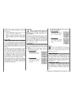
In order to delete the set support points 1 to 5,
move the vertical green line with the control stick
next to the relevant support point. Once the sup-
port point number appears along with the associ-
ated value in the line "POINT" and the point is red
(see the screen-shot below), you can delete it by
touching the
ENT
button, for example:
Touch
Changing the support point value
•
X-axis
button
(X-axis)
Activate this function by touching the button at
the bottom edge of the display. The button color
changes from black to blue:
You can then move an active (red) point to the right
with the
+
button, and to the left with the
–
but-
ton, for example:
155
Function menu | Helicopter model - Pitch curve
Summary of Contents for mz-24 PRO
Page 13: ...13 Personal notes...
Page 19: ...19 Personal notes...
Page 37: ...37 Personal notes...
Page 59: ...Touch 59 Base menu Model selection...
Page 79: ...79 Personal notes...
Page 89: ...89 Personal notes...
Page 115: ...115 Personal notes...
Page 153: ...Helicopter model function menus Common function menus 153 Personal notes...
Page 169: ...169 Personal notes...
Page 187: ...187 Personal notes...
Page 199: ...199 Personal notes...
Page 207: ...Fixed wing model function menus System menus 207 Personal notes...
Page 211: ...211 Personal notes...
Page 219: ...219 Personal notes...
Page 237: ...237 Personal notes...
Page 238: ...238 Personal notes...
Page 239: ...239 Personal notes...


