the receiver. As long as the LED is dark, the receiv-
er is in binding mode.
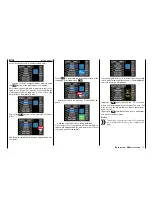
As described above, within this 3 second win-
dow, start binding the receiver to the current mod-
el memory by touching one of the two buttons in
the "BIND ON/OFF" line with a finger or the provid-
ed stylus, for example.
Binding has been successful if the receiver LED
remains dark and the receiver display switches to
6CH
.
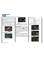
If the red receiver LED shines red again, the bind-
ing process was unsuccessful. At the same time,
OFF
appears again in the line "BIND ON/OFF".
Change the positions of the associated antennas
and try the entire procedure again.
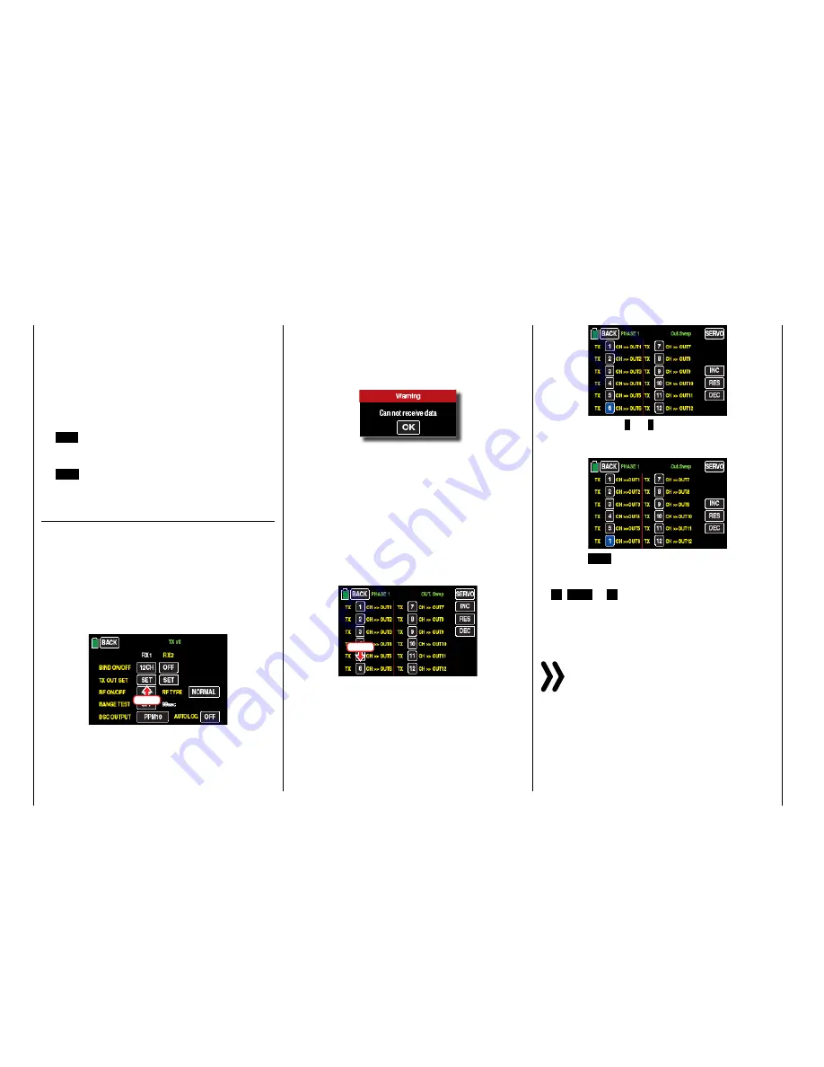
Out.Swap
(receiver output)
As mentioned in the introduction to the section "Bind-
ing receivers", the
mz-24
HoTT Pro transmitter allow
you use this menu item to distribute the transmitter
control channels
within a receiver
as desired, and you
can also distribute the 12 receiver control channels to
the
two receivers
as preferred. This distribution will be
termed mapping or channel mapping in the following.
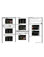
Touch the receiver (such as "RX1") to be mapped in
the line
Out.Swap
:
Touch
• If there is no other reaction than a "beep", the RF
module is switched off. Switch the RF module on
and repeat the process.
• If a pop-up display appears with the warning text
...
... the RF module of your transmitter is switched on
but there is no connection with the receiver. Then
switch the receiver system on and/or bind correct-
ly the receiver and repeat the process.
Channel assignment within a receiver
Like the channel mapping described in "
Channel
Mapping
" (also termed "channel mapping" in the "
Te-
lemetry
" menu), you can easily distribute transmitter
control channels at the receiver inputs to the outputs,
or servo connections, of the selected receiver, for ex-
ample:
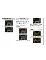
Touch
After selecting the desired
output
the respective servo
output of the receiver to map by tapping on the relat-
ed channel button, the color of the selected button
changes from black to blue:
Repeatedly touch
+
or
–
to select the desired input
channel related
Transmitter output
(see page ), for ex-
ample:
Touch the
RES
button to reset a changed output to
the default mapping.
The value modified by touching one of the three later-
al
+
,
RES
or
–
buttons will be automatically trans-
mitted to the related receiver.
Use the same procedure to switch other control chan-
nel/receiver output combinations.
Notice
If for example you entered "2AILE" in the basic
settings for a model, the transmitter assigns con-
trol function 2 (aileron) to control channels 2+5 for
the left and right aileron. The corresponding transmitter
outputs (= receiver inputs) to be mapped would in this
case be channels 2+5 (see the examples below).
70
Base menu - Transmitter setting
Summary of Contents for mz-24 PRO
Page 13: ...13 Personal notes...
Page 19: ...19 Personal notes...
Page 37: ...37 Personal notes...
Page 59: ...Touch 59 Base menu Model selection...
Page 79: ...79 Personal notes...
Page 89: ...89 Personal notes...
Page 115: ...115 Personal notes...
Page 153: ...Helicopter model function menus Common function menus 153 Personal notes...
Page 169: ...169 Personal notes...
Page 187: ...187 Personal notes...
Page 199: ...199 Personal notes...
Page 207: ...Fixed wing model function menus System menus 207 Personal notes...
Page 211: ...211 Personal notes...
Page 219: ...219 Personal notes...
Page 237: ...237 Personal notes...
Page 238: ...238 Personal notes...
Page 239: ...239 Personal notes...


