Airbrake
Adjusting the braking system of airplanes
This sub-menu is displayed, according to the selected
model type and its configuration.
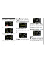
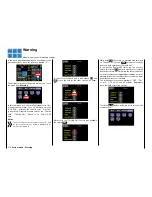
In the basic transmitter display, use your finger or the
provided stylus to touch the gear icon labeled "F":
Touch
The display switches to the blue function menu. Touch
the menu item "
Airbrake
".
Touch
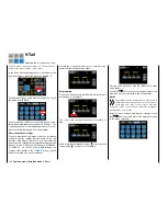
Depending on the selected number of ailerons and
flaps, the display shows different views: The top of the
two following figures shows the display when setting
the minimum "2AILE", and the bottom figure shows
the display when selecting the maximum "... 4FLAP".
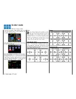
Phase-dependent settings
The here mentioned sub-menu offers the possibility
of phase specific settings. Recognizable on the top
left side of the display in green color is displayed the
phase name. As standard is displayed the name of the
phase 1, which is indicated by the name "NORMAL"
or "PHASE 1". As soon as you will have defined one
or many other phases in the "
PHASE
" menu, you will
be able to switch among those phases. Activate the
corresponding switch or switches if desired to switch
between the phases.
Programming
In the display described below, enter the amount and
direction of the deflection of your flaps, and possibly
also the elevator, for braking. In order for these set-
tings to be effective and retrievable with a switch, for
example, start programming the option fields "ACT"
and "Ctrl/sw" described below:
• ACT column
(active)
Within the value field for this column, specify
phase specifically whether this function is gener-
ally blocked (
INH
) or
ON
.
Once you set this value field to
ON
, you can turn
the effect of the selected control element on the
flap position for specific phases individually on and
off with a control assigned in the option field "Ctrl/
sw".
• Ctrl/sw option
(control/switch)
In the value field in the Ctrl/sw column, you as-
sign a control or control switch for a specific phase
to the mixer as described in the section
Control
and switch assignment
, for example in the phase
"LANDING":
RATE line
A symmetrical or an asymmetrical effect can be de-
fined for each flap pair. In order to be able to define
upward and downward deflections, the setting range
is ±150%.
Switch to the desired phase, such as "LANDING", and
touch the value field to be set.
200
Function menu | Airplane models - brakes
Summary of Contents for mz-24 PRO
Page 13: ...13 Personal notes...
Page 19: ...19 Personal notes...
Page 37: ...37 Personal notes...
Page 59: ...Touch 59 Base menu Model selection...
Page 79: ...79 Personal notes...
Page 89: ...89 Personal notes...
Page 115: ...115 Personal notes...
Page 153: ...Helicopter model function menus Common function menus 153 Personal notes...
Page 169: ...169 Personal notes...
Page 187: ...187 Personal notes...
Page 199: ...199 Personal notes...
Page 207: ...Fixed wing model function menus System menus 207 Personal notes...
Page 211: ...211 Personal notes...
Page 219: ...219 Personal notes...
Page 237: ...237 Personal notes...
Page 238: ...238 Personal notes...
Page 239: ...239 Personal notes...


