Pitch curve
Phase-specific setting of the pitch control curve
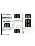
In the basic transmitter display, use your finger or the
provided stylus to touch the gear icon labeled "F":
Touch
The display switches to the blue function menu. Touch
the menu item "
PIT.CRV
".
Touch
For the setting of the pitch curve there is a curve mixer
available in every flight phase. In this mixer can how-
ever only be programmed if required also not linear
mixer actions analog to the control stick travels.
"Pitch min" line
In the helicopter program for the
mz-24
HoTT Pro
transmitter, the "rear" throttle position is the "Pitch
min." position by default.
Through this option you can easily reverse the control
direction of the pitch control stick from the standard
pre-set position "pitch min back" to "pitch min for-
ward", and vice versa, by tapping on the
BACK
or
FORWARD
button in the "Pitch min" line:
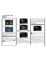
Touch
The warning note appears:
Touch
NO
to terminate the procedure. Touch
YES
to
confirm the procedure which changes the direction of
travel of the pitch control stick:
Such an inverted control signal acts on all following
mixed and coupling functions and the active Power
OFF time of the Thro Position.
Phase-dependent settings of the pitch curves
The here mentioned sub-menu offers the possibility
of phase specific settings. Recognizable on the top
left side of the display in green color is displayed the
phase name.
As standard is displayed the name of the phase
1, which is indicated by the name "NORMAL" or
"PHASE 1". As soon as you will have defined one or
many other phases in the "
PHASE
" menu, you will
be able to switch among those phases. Activate the
corresponding switch or switches if desired to switch
between the phases.
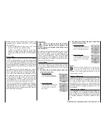
Setting the pitch curve
In this display, you can adapt the pitch curve as need-
ed, depending on the phase if desired:
Notice
In the display graph will be represented the curve
characteristics directly and completely inde-
pendently from the actually selected direction of
the pitch control stick.
The pitch control curve can be specified by up to 7
points, the so-called support points, along the entire
control stick travel.
At the beginning, fewer support points are required to
set the pitch curve. It is, however, highly recommend-
able to start with three support points.
These three endpoints, the two endpoints "Pitch low
(L)" = -100% control travel and "Pitch high (H)" =
+100% control travel, as well as a point to be placed
in the control, center describe a linear characteristic
for the pitch control curve.
154
Function menu | Helicopter model - Pitch curve
Summary of Contents for mz-24 PRO
Page 13: ...13 Personal notes...
Page 19: ...19 Personal notes...
Page 37: ...37 Personal notes...
Page 59: ...Touch 59 Base menu Model selection...
Page 79: ...79 Personal notes...
Page 89: ...89 Personal notes...
Page 115: ...115 Personal notes...
Page 153: ...Helicopter model function menus Common function menus 153 Personal notes...
Page 169: ...169 Personal notes...
Page 187: ...187 Personal notes...
Page 199: ...199 Personal notes...
Page 207: ...Fixed wing model function menus System menus 207 Personal notes...
Page 211: ...211 Personal notes...
Page 219: ...219 Personal notes...
Page 237: ...237 Personal notes...
Page 238: ...238 Personal notes...
Page 239: ...239 Personal notes...


