background image

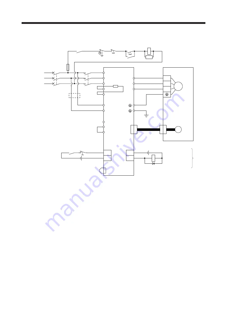
3. SIGNALS AND WIRING 

3 -  7 

 
(4) MR-J4-700TM 

C

P+

L11

L21

P3

P4

N-

L1

L2

L3

U

V

W

U

V

W

M

CN2

MC

MC

SK

CN8

MCCB

ALM

DOCOM

CN3

RA1

CN3

EM2

DICOM

Built-in

regenerative

resistor

MC

(Note 7)

(Note 5)

24 V DC (Note 12)

Malfunction (Note 4)

3-phase
200 V AC to
240 V AC

Servo amplifier

(Note 1)

(Note 10)

(Note 2)

Servo motor

Motor

Encoder

(Note 3)

Encoder

cable

(Note 6)

(Note 4)

Malfunction

RA1

OFF

ON

Emergency stop switch

(Note 5) Forced stop 2

(Note 9)

Short-circuit connector

(Packed with the servo amplifier)

(Note 8)

Main circuit power supply

(Note 11)

(Note 11)

24 V DC (Note 12)


Note   1.  Between P3 and P4 is connected by default. When using the power factor improving DC reactor, remove the short bar 

between P3 and P4. Refer to section 11.11 for details. Additionally, a power factor improving DC reactor and power factor 
improving AC reactor cannot be used simultaneously. 


  2.  When using the regenerative option, refer to section 11.2. 


  3.  For the encoder cable, use of the option cable is recommended. For selecting cables, refer to "Servo Motor Instruction Manual 

(Vol. 3)". 


  4.  If disabling ALM (Malfunction) output with the parameter, configure up the power supply circuit which switches off the magnetic 

contactor after detection of alarm occurrence on the controller side. 


  5.  This diagram is for sink I/O interface. For source I/O interface, refer to section 3.8.3. 


  6.  For connecting servo motor power wires, refer to "Servo Motor Instruction Manual (Vol. 3)". 


  7.  Use a magnetic contactor with an operation delay time (interval between current being applied to the coil until closure of 

contacts) of 80 ms or less. Depending on the main circuit voltage and operation pattern, bus voltage decreases, and that may 
cause the forced stop deceleration to shift to the dynamic brake deceleration. When dynamic brake deceleration is not 
required, slow the time to turn off the magnetic contactor. 


  8.  Configure a circuit to turn off EM2 when the main circuit power is turned off to prevent an unexpected restart of the servo 

amplifier. 


  9.  When not using the STO function, attach the short-circuit connector came with a servo amplifier. 


10.  When wires used for L11 and L21 are thinner than wires used for L1, L2, and L3, use a molded-case circuit breaker. (Refer to 

section 11.10.) 


11.  Connecting a servo motor of the wrong axis to U, V, W, or CN2 of the servo amplifier may cause a malfunction. 


12.  The illustration of the 24 V DC power supply is divided between input signal and output signal for convenience. However, they 

can be configured by one. 


Содержание MR-J4 TM Series

Страница 1: ...thout notice This Instruction Manual uses recycled paper MODEL MODEL CODE General Purpose AC Servo MR J4 _TM_ SERVO AMPLIFIER INSTRUCTION MANUAL HEAD OFFICE TOKYO BLDG MARUNOUCHI TOKYO 100 8310 MODEL MR J4 _TM_ Multi network Interface AC Servo SERVO AMPLIFIER INSTRUCTION MANUAL C C ...

Страница 2: ... or severe injury CAUTION Indicates that incorrect handling may cause hazardous conditions resulting in medium or slight injury to personnel or may cause physical damage Note that the CAUTION level may lead to a serious consequence according to conditions Please follow the instructions of both levels because they are important to personnel safety What must not be done and what must be done are ind...

Страница 3: ...insulate the connections of the power supply terminals 2 To prevent fire note the following CAUTION Install the servo amplifier servo motor and regenerative resistor on incombustible material Installing them directly or close to combustibles will lead to smoke or a fire Always connect a magnetic contactor between the power supply and the main circuit power supply L1 L2 and L3 of the servo amplifie...

Страница 4: ...areas of the servo amplifier Otherwise it may cause a malfunction Do not drop or strike the servo amplifier and servo motor Isolate them from all impact loads When you keep or use the equipment please fulfill the following environment Items Environment Ambient temperature Operation 0 C to 55 C non freezing Storage 20 C to 65 C non freezing Ambient humidity Operation 90 RH or less non condensing St...

Страница 5: ...utput should be fitted in the specified direction Otherwise the emergency stop and other protective circuits may not operate DOCOM 24 V DC Servo amplifier RA For sink output interface Control output signal DOCOM Control output signal 24 V DC Servo amplifier RA For source output interface When the cable is not tightened enough to the terminal block the cable or terminal block may generate heat beca...

Страница 6: ...ture e g where a ball screw and the servo motor are coupled via a timing belt the electromagnetic brake may not hold the motor shaft To ensure safety install a stopper on the machine side 5 Corrective actions CAUTION Ensure safety by confirming the power off etc before performing corrective actions Otherwise it may cause an accident When it is assumed that a hazardous condition may occur due to a ...

Страница 7: ... be installed as specified Operation must be performed in accordance with this Specifications and Instruction Manual DISPOSAL OF WASTE Please dispose a servo amplifier battery primary battery and other options according to your local laws and regulations EEP ROM life The number of write times to the EEP ROM which stores parameter settings etc is limited to 100 000 If the total number of the follow...

Страница 8: ...ote 3 SH NA 030112 MELSERVO Linear Encoder Instruction Manual Note 2 4 SH NA 030111 EMC Installation Guidelines IB NA 67310 Note 1 It is necessary for using a rotary servo motor 2 It is necessary for using a linear servo motor 3 It is necessary for using a direct drive motor 4 It is necessary for using a fully closed loop system 5 It is necessary for using an MR D30 functional safety unit Wiring W...

Страница 9: ...A 8 MEMO ...

Страница 10: ...iers at altitude exceeding 1000 m and up to 2000 m above sea level 2 6 3 SIGNALS AND WIRING 3 1 to 3 42 3 1 Input power supply circuit 3 3 3 1 1 200 V class 3 4 3 1 2 400 V class 3 10 3 1 3 100 V class 3 14 3 2 I O signal connection example 3 15 3 2 1 For sink I O interface 3 15 3 2 2 For source I O interface 3 16 3 3 Explanation of power supply system 3 17 3 3 1 Signal explanations 3 17 3 3 2 Pow...

Страница 11: ...17 5 PARAMETERS 5 1 to 5 86 5 1 Parameter list 5 1 5 1 1 Basic setting parameters Pr PA_ _ 5 2 5 1 2 Gain filter setting parameters Pr PB_ _ 5 3 5 1 3 Extension setting parameters Pr PC_ _ 5 4 5 1 4 I O setting parameters Pr PD_ _ 5 7 5 1 5 Extension setting 2 parameters Pr PE_ _ 5 8 5 1 6 Extension setting 3 parameters Pr PF_ _ 5 9 5 1 7 Linear servo motor DD motor setting parameters Pr PL_ _ 5 1...

Страница 12: ...ONS 7 1 to 7 38 7 1 Filter setting 7 1 7 1 1 Machine resonance suppression filter 7 2 7 1 2 Adaptive filter II 7 5 7 1 3 Shaft resonance suppression filter 7 7 7 1 4 Low pass filter 7 8 7 1 5 Advanced vibration suppression control II 7 8 7 1 6 Command notch filter 7 13 7 2 Gain switching function 7 15 7 2 1 Applications 7 15 7 2 2 Function block diagram 7 16 7 2 3 Parameter 7 17 7 2 4 Gain switchi...

Страница 13: ...setting 11 11 11 2 4 Selection of regenerative option 11 11 11 2 5 Dimensions 11 16 11 3 FR BU2 H brake unit 11 20 11 3 1 Selection 11 20 11 3 2 Brake unit parameter setting 11 21 11 3 3 Connection example 11 22 11 3 4 Dimensions 11 30 11 4 FR RC H power regeneration converter 11 33 11 5 FR CV H power regeneration common converter 11 37 11 5 1 Model designation 11 38 11 5 2 Selection 11 38 11 6 Ju...

Страница 14: ...ks of the STO function 13 2 13 1 5 Specifications 13 3 13 1 6 Maintenance 13 4 13 2 STO I O signal connector CN8 and signal layouts 13 4 13 2 1 Signal layouts 13 4 13 2 2 Signal device explanations 13 5 13 2 3 How to pull out the STO cable 13 5 13 3 Connection example 13 6 13 3 1 Connection example for CN8 connector 13 6 13 3 2 External I O signal connection example using an MR J3 D05 safety logic...

Страница 15: ...2 Power supply capacity and generated loss 15 18 15 4 3 Dynamic brake characteristics 15 19 16 FULLY CLOSED LOOP SYSTEM 16 1 to 16 20 16 1 Functions and configuration 16 1 16 1 1 Function block diagram 16 1 16 1 2 Selecting procedure of control mode 16 2 16 1 3 System configuration 16 3 16 2 Load side encoder 16 4 16 2 1 Linear encoder 16 4 16 2 2 Rotary encoder 16 4 16 2 3 Configuration diagram o...

Страница 16: ...PENDIX App 1 to App 52 App 1 When using the servo amplifier with the DC power supply input App 1 App 2 Handling of AC servo amplifier batteries for the United Nations Recommendations on the Transport of Dangerous Goods App 5 App 3 Symbol for the new EU Battery Directive App 8 App 4 Compliance with global standards App 9 App 5 MR J3 D05 Safety logic unit App 22 App 6 EC declaration of conformity Ap...

Страница 17: ...8 MEMO ...

Страница 18: ...maintenance support function detects an error in the machine parts This function provides strong support for the machine maintenance and inspection The MR J4 _TM_ servo amplifier supports the Safe Torque Off STO function By combining with optional MR J3 D05 the servo amplifier supports Safe stop 1 SS1 function The MR J4 _TM_ servo amplifier has a USB communication interface Therefore you can conne...

Страница 19: ...CT AB6916 C Note 2 EtherNet IP Note 1 ABCC M40 EIP AB6927 C Note 1 This is used with servo amplifiers with software version B0 or later 2 AB6916 B and AB6916 C are available However when using servo amplifiers with software version B0 or later in combination with the network modules with software version 1 11 01 or earlier use EtherCAT Slave Information ESI Without ESI the controller does not reco...

Страница 20: ...on Note 2 Power supply MC MCCB Base amplifier STO circuit CN5 USB USB Personal computer D A Analog monitor 2 channels Position command input CN3 Servo amplifier U V W U V W P3 P4 Diode stack Relay P B RA 24 V DC B1 B2 Battery for absolute position detection system CN4 STO switch Model speed Model torque M CN2 CN8 Control circuit power supply Model position control Model speed control I F Control S...

Страница 21: ... the power supply to L1 and L3 Leave L2 open Refer to section 1 3 for the power supply specifications 3 Servo amplifiers MR J4 70TM or more have a cooling fan 4 The power factor improving AC reactor can also be used In this case the power factor improving DC reactor cannot be used When not using the power factor improving DC reactor short P3 and P4 ...

Страница 22: ...C Encoder Model position Current control Actual position control Actual speed control Virtual motor Virtual encoder Position command input Model speed Model torque Model position control Model speed control Step down circuit Battery for absolute position detection system I F Control Personal computer Analog monitor 2 channels Digital I O control Note 2 Diode stack CN2L External encoder Network mod...

Страница 23: ...rcuit Battery for absolute position detection system External encoder Cooling fan Note 1 Power supply STO circuit Servo amplifier Control circuit power supply CHARGE lamp Regene rative TR Current detection Overcurrent protection Voltage detection Base amplifier STO switch Diode stack Model position Current control Actual position control Actual speed control Virtual motor Virtual encoder Position ...

Страница 24: ...n the entire equipment For alarms for which the servo motor does not decelerate to stop refer to chapter 8 3 The power factor improving AC reactor can also be used In this case the power factor improving DC reactor cannot be used When not using the power factor improving DC reactor short P3 and P4 4 The external dynamic brake cannot be used for compliance with SEMI F47 standard Do not assign DB Dy...

Страница 25: ... absolute position detection system CN4 STO switch Model speed Model torque M CN2 CN8 Control circuit power supply Model position control Model speed control IF Control Servo motor Charge lamp Regene rative TR Current detector Digital I O control Regenerative option U U U Step down circuit Note 3 Power factor improving DC reactor Electromagnetic brake CN2L External encoder Network module Controlle...

Страница 26: ...odel position control Model speed control Servo motor Regenerative option L3 L2 L1 U U U Step down circuit Note 2 Power factor improving DC reactor Charge lamp Regene rative TR Electromagnetic brake Model position Model speed Model torque Current control Actual position control Actual speed control IF Control Personal computer Analog monitor 2 channels Digital I O control CN2L External encoder Net...

Страница 27: ...ctor improving DC reactor Charge lamp Regene rative TR Encoder Current detection Overcurrent protection Voltage detection Base amplifier STO circuit STO switch Control circuit power supply Electromagnetic brake Virtual motor Virtual encoder Position command input Battery For absolute position detection system Model position control Model speed control Step down circuit Model position Model speed M...

Страница 28: ...n the entire equipment For alarms for which the servo motor does not decelerate to stop refer to chapter 8 3 The power factor improving AC reactor can also be used In this case the power factor improving DC reactor cannot be used When not using the power factor improving DC reactor short P3 and P4 4 The external dynamic brake cannot be used for compliance with SEMI F47 standard Do not assign DB Dy...

Страница 29: ...put CN3 Servo amplifier U V W U V W Diode stack Relay P B RA 24 V DC B1 B2 Battery for absolute position detection system CN4 STO switch Model speed Model torque M CN2 CN8 Control circuit power supply Model position control Model speed control IF Control Servo motor Charge lamp Regene rative TR Current encoder Digital I O control Regenerative option U Step down circuit External encoder CN2L Electr...

Страница 30: ...C input 1 phase 200 V AC to 240 V AC 50 Hz 60 Hz At DC input Note 8 283 V DC to 340 V DC Rated current A 0 2 0 3 Permissible voltage fluctuation At AC input 1 phase 170 V AC to 264 V AC At DC input Note 8 241 V DC to 374 V DC Permissible frequency fluctuation Within 5 Power consumption W 30 45 Inrush current A Refer to section 10 5 Interface power supply Voltage 24 V DC 10 Current capacity A Note ...

Страница 31: ...s are used The current capacity can be decreased by reducing the number of I O points 2 When closely mounting the servo amplifier operate it at an ambient temperature of 0 C to 45 C or at 75 or smaller effective load ratio 3 Test pulse is a signal which instantaneously turns off a signal to the servo amplifier at a constant period for external circuit to self diagnose 4 Except for the terminal blo...

Страница 32: ...ulse Analog monitor Two channels Protective functions Overcurrent shut off regenerative overvoltage shut off overload shut off electronic thermal servo motor overheat protection encoder error protection regenerative error protection undervoltage protection instantaneous power failure protection overspeed protection error excessive protection magnetic pole detection protection and linear servo cont...

Страница 33: ... safety level depends on the setting value of Pr PF18 STO diagnosis error detection time and whether STO input diagnosis by TOFB output is performed or not For details refer to the Function column of Pr PF18 in section 5 2 6 6 Use an external dynamic brake for this servo amplifier Failure to do so will cause an accident because the servo motor does not stop immediately but coasts at emergency stop...

Страница 34: ... channels Protective functions Overcurrent shut off regenerative overvoltage shut off overload shut off electronic thermal servo motor overheat protection encoder error protection regenerative error protection undervoltage protection instantaneous power failure protection overspeed protection error excessive protection magnetic pole detection protection and linear servo control error protection Fu...

Страница 35: ...s a signal which instantaneously turns off a signal to the servo amplifier at a constant period for external circuit to self diagnose 4 Except for the terminal block 5 Follow the restrictions in section 2 6 when using the servo amplifiers at altitude exceeding 1000 m and up to 2000 m above sea level 6 The safety level depends on the setting value of Pr PF18 STO diagnosis error detection time and w...

Страница 36: ...2SS1 LM U2PAD 10M 0SS0 LM U2PAF 15M 0SS0 TM RFM004C20 MR J4 60TM 51 52 53 LM U2PBD 15M 1SS0 TM RFM006C20 TM RFM006E20 MR J4 70TM 73 73 72 73 LM H3P3B 24P CSS0 LM H3P3C 36P CSS0 LM H3P7A 24P ASS0 LM K2P2A 02M 1SS1 LM U2PBF 22M 1SS0 TM RFM012E20 TM RFM012G20 TM RFM040J10 MR J4 100TM 81 102 103 53 TM RFM018E20 MR J4 200TM 121 201 152 202 152 103 153 153 203 73 103 LM H3P3D 48P CSS0 LM H3P7B 48P ASS0 ...

Страница 37: ... 500TM4 5024 5034 3534 MR J4 700TM4 7024 6014 701M4 7034 5034 MR J4 11KTM4 8014 12K14 11K1M4 9034 MR J4 15KTM4 15K14 15K1M4 MR J4 22KTM4 20K14 25K14 22K1M4 LM FP5H 60M 1SS0 3 100 V class Servo amplifier Rotary servo motor Linear servo motor primary side Direct drive motor HG KR HG MR MR J4 10TM1 053 13 053 13 MR J4 20TM1 23 23 LM U2PAB 05M 0SS0 LM U2PBB 07M 1SS0 TM RFM002C20 MR J4 40TM1 43 43 LM H...

Страница 38: ... 4194304 pulses rev is used for the encoder of the rotary servo motor compatible with the MELSERVO J4 series Absolute position detection system Setting a home position once makes home position return unnecessary at every power on Chapter 12 Gain switching function You can switch gains during rotation stop and can use input devices to switch gains during operation Section 7 2 Advanced vibration sup...

Страница 39: ...red to drive a direct drive motor Chapter 15 Fully closed loop system Fully closed loop system can be configured using the load side encoder Chapter 16 One touch tuning Gain adjustment is performed just by one click a certain button on MR Configurator2 Also one touch tuning can be performed via a network For details refer to the MR J4 _TM_ Servo Amplifier Instruction Manual for each communication ...

Страница 40: ...ifier Instruction Manual for each communication method Scale measurement function The function transmits position information of a scale measurement encoder to the controller by connecting the scale measurement encoder in semi closed loop control This is available with servo amplifiers with software version B0 or later Check the software version using MR Configurator2 Section 17 1 MR D30 functiona...

Страница 41: ...ons of the symbols are available Series Rated output Multi network interface Special specifications Symbol Rated output kW 10 0 1 20 0 2 40 0 4 Symbol Special specifications None Standard 60 0 6 70 0 75 100 1 200 2 350 3 5 500 5 700 7 11K 11 15K 15 22K 22 Power supply Symbol Power supply None 3 phase or 1 phase 200 V AC to 240 V AC 4 3 phase 380 V AC to 480 V AC 1 1 phase 100 V AC to 120 V AC MR J...

Страница 42: ...tible external encoders Section 3 4 Servo Motor Instruction Manual Vol 3 9 Note External encoder connector CN2L Used to connect the external encoder Refer to table 1 1 for connections of external encoders Section 3 4 Linear Encoder Instruction Manual 10 Battery connector CN4 Used to connect the battery for absolute position data backup Chapter 12 11 Battery holder Install the battery for absolute ...

Страница 43: ...ting plate Section 1 6 3 Servo motor power output connector CNP3 Connect the servo motor Section 3 1 Section 3 3 4 Control circuit power connector CNP2 Connect the control circuit power supply and regenerative option 5 Charge lamp When the main circuit is charged this will light While this lamp is lit do not reconnect the cables 6 Protective earth PE terminal Section 3 1 Section 3 3 7 Battery hold...

Страница 44: ...input power supply 3 Battery holder Install the battery for absolute position data backup Section 12 2 4 Rating plate Section 1 6 5 Regenerative option power factor improving reactor terminal block TE3 Used to a connect a regenerative option and a power factor improving DC reactor Section 3 1 Section 3 3 6 Servo motor power output terminal block TE4 Connect the servo motor 7 Charge lamp When the m...

Страница 45: ...tor Section 3 1 Section 3 3 2 Main circuit terminal block TE1 Used to connect the input power supply regenerative option and servo motor 3 Control circuit terminal block TE2 Used to connect the control circuit power supply 4 Protective earth PE terminal 5 Battery holder Install the battery for absolute position data backup Section 12 2 6 Rating plate Section 1 6 7 Charge lamp When the main circuit...

Страница 46: ...ving DC reactor and a regenerative option Section 3 1 Section 3 3 2 Main circuit terminal block TE1 1 Used to connect the input power supply and servo motor 3 Control circuit terminal block TE2 Used to connect the control circuit power supply 4 Protective earth PE terminal 5 Battery holder Install the battery for absolute position data backup Section 12 2 6 Rating plate Section 1 6 7 Charge lamp W...

Страница 47: ...C reactor and a regenerative option Section 3 1 Section 3 3 2 Main circuit terminal block TE1 1 Used to connect the input power supply and servo motor 3 Control circuit terminal block TE2 Used to connect the control circuit power supply 4 Protective earth PE terminal 5 Battery holder Install the battery for absolute position data backup Section 12 2 6 Rating plate Section 1 6 7 Charge lamp When th...

Страница 48: ...ders Section 3 4 Servo Motor Instruction Manual Vol 3 9 Note External encoder connector CN2L Used to connect the external encoder Refer to table 1 1 for connections of external encoders Section 3 4 Linear Encoder Instruction Manual 10 Battery connector CN4 Used to connect the battery for absolute position data backup Chapter 12 11 Battery holder Install the battery for absolute position data backu...

Страница 49: ...power connector CNP2 Connect the control circuit power supply and regenerative option Section 3 1 Section 3 3 4 Servo motor power output connector CNP3 Connect the servo motor 5 Charge lamp When the main circuit is charged this will light While this lamp is lit do not reconnect the cables 6 Protective earth PE terminal Section 3 1 Section 3 3 7 Battery holder Install the battery for absolute posit...

Страница 50: ...ain circuit terminal block TE1 Used to connect the input power supply regenerative option and servo motor 3 Battery holder Install the battery for absolute position data backup Section 12 2 4 Rating plate Section 1 6 5 Power factor improving reactor terminal block TE3 Used to connect a power factor improving DC reactor Section 3 1 Section 3 3 6 Charge lamp When the main circuit is charged this wil...

Страница 51: ...ctor Section 3 1 Section 3 3 2 Main circuit terminal block TE1 Used to connect the input power supply regenerative option and servo motor 3 Control circuit terminal block TE2 Used to connect the control circuit power supply 4 Protective earth PE terminal 5 Battery holder Install the battery for absolute position data backup Section 12 2 6 Rating plate Section 1 6 7 Charge lamp When the main circui...

Страница 52: ...oving DC reactor and a regenerative option Section 3 1 Section 3 3 2 Main circuit terminal block TE1 1 Used to connect the input power supply and servo motor 3 Control circuit terminal block TE2 Used to connect the control circuit power supply 4 Protective earth PE terminal 5 Battery holder Install the battery for absolute position data backup Section 12 2 6 Rating plate Section 1 6 7 Charge lamp ...

Страница 53: ...DC reactor and a regenerative option Section 3 1 Section 3 3 2 Main circuit terminal block TE1 1 Used to connect the input power supply and servo motor 3 Control circuit terminal block TE2 Used to connect the control circuit power supply 4 Protective earth PE terminal 5 Battery holder Install the battery for absolute position data backup Section 12 2 6 Rating plate Section 1 6 7 Charge lamp When t...

Страница 54: ... 3 4 Servo Motor Instruction Manual Vol 3 9 Note External encoder connector CN2L Used to connect the external encoder Refer to table 1 1 for connections of external encoders Section 3 4 Linear Encoder Instruction Manual 10 Battery connector CN4 Used to connect the battery for absolute position data backup Chapter 12 11 Battery holder Install the battery for absolute position data backup Section 12...

Страница 55: ...d others Otherwise an electric shock may occur In addition when confirming whether the charge lamp is off or not always confirm it from the front of the servo amplifier The following shows how to remove and reinstall the front cover of MR J4 700TM to MR J4 22KTM and MR J4 500TM4 to MR J4 22KTM4 The diagram is for MR J4 700TM 1 Removal of the front cover A A 1 Hold the ends of lower side of the fro...

Страница 56: ...he front cover Front cover setting tab A A 1 Insert the front cover setting tabs into the sockets of servo amplifier 2 places 2 Push down the cover supporting at point A Setting tab 3 Press the cover against the terminal box until the installing knobs click ...

Страница 57: ...hock may occur In addition when confirming whether the charge lamp is off or not always confirm it from the front of the servo amplifier CAUTION Avoid installing and removing the network module repeatedly Any contact failure of the connector may be caused POINT The internal circuits of the servo amplifier and the network module may be damaged by static electricity Always take the following precaut...

Страница 58: ...onfirmation hole in the same manner as the upper hole Network module tab Confirmation hole The network module tab hits the board end face and the module is incompletely inserted Check that the network module tab can be confirmed through the confirmation hole The network module tab cannot be confirmed through the confirmation hole Fixing screw 6 lobe screw 3 Check if the network module tabs can be ...

Страница 59: ...rk module approximately 5 mm using the 8 6 lobe driver Hook the slot cover on the loosened screws 2 Hook the slot cover included at product shipment on the loosened screws as shown in the diagram 3 Hold the slot cover and pull it straight toward you to remove the network module 4 Fit the slot cover to prevent dust from entering it ...

Страница 60: ...UTION Connecting a servo motor of the wrong axis to U V W or CN2 of the servo amplifier may cause a malfunction POINT Equipment other than the servo amplifier and servo motor are optional or recommended products When using the servo amplifier with the DC power supply input refer to app 1 ...

Страница 61: ...actor short P3 and P4 2 For 1 phase 200 V AC to 240 V AC connect the power supply to L1 and L3 Leave L2 open Refer to section 1 3 for the power supply specifications 3 Depending on the main circuit voltage and operation pattern bus voltage decreases and that may cause the forced stop deceleration to shift to the dynamic brake deceleration When dynamic brake deceleration is not required slow the ti...

Страница 62: ... improving DC reactor short P3 and P4 2 Refer to section 1 3 for the power supply specifications 3 Depending on the main circuit voltage and operation pattern bus voltage decreases and that may cause the forced stop deceleration to shift to the dynamic brake deceleration When dynamic brake deceleration is not required slow the time to turn off the magnetic contactor 4 When using servo amplifier in...

Страница 63: ...improving DC reactor short P3 and P4 2 Refer to section 1 3 for the power supply specifications 3 Depending on the main circuit voltage and operation pattern bus voltage decreases and that may cause the forced stop deceleration to shift to the dynamic brake deceleration When dynamic brake deceleration is not required slow the time to turn off the magnetic contactor 4 When using servo amplifier in ...

Страница 64: ...ng the power factor improving DC reactor short P3 and P4 2 Refer to section 1 3 for the power supply specifications 3 Depending on the main circuit voltage and operation pattern bus voltage decreases and that may cause the forced stop deceleration to shift to the dynamic brake deceleration When dynamic brake deceleration is not required slow the time to turn off the magnetic contactor 4 When using...

Страница 65: ...ot using the power factor improving DC reactor short P3 and P4 2 Refer to section 1 3 for the power supply specifications 3 Depending on the main circuit voltage and operation pattern bus voltage decreases and that may cause the forced stop deceleration to shift to the dynamic brake deceleration When dynamic brake deceleration is not required slow the time to turn off the magnetic contactor 4 When...

Страница 66: ...ng the power factor improving DC reactor short P3 and P4 2 Refer to section 1 3 for the power supply specifications 3 Depending on the main circuit voltage and operation pattern bus voltage decreases and that may cause the forced stop deceleration to shift to the dynamic brake deceleration When dynamic brake deceleration is not required slow the time to turn off the magnetic contactor 4 When using...

Страница 67: ... used When not using the power factor improving DC reactor short P3 and P4 2 Refer to section 1 3 for the power supply specification 3 Depending on the main circuit voltage and operation pattern bus voltage decreases and that may cause the forced stop deceleration to shift to the dynamic brake deceleration When dynamic brake deceleration is not required slow the time to turn off the magnetic conta...

Страница 68: ...or improving DC reactor short P3 and P4 2 Refer to section 1 3 for the power supply specification 3 Depending on the main circuit voltage and operation pattern bus voltage decreases and that may cause the forced stop deceleration to shift to the dynamic brake deceleration When dynamic brake deceleration is not required slow the time to turn off the magnetic contactor 4 When using servo amplifier i...

Страница 69: ...using the power factor improving DC reactor short P3 and P4 2 Refer to section 1 3 for the power supply specification 3 Depending on the main circuit voltage and operation pattern bus voltage decreases and that may cause the forced stop deceleration to shift to the dynamic brake deceleration When dynamic brake deceleration is not required slow the time to turn off the magnetic contactor 4 When usi...

Страница 70: ...sing the power factor improving DC reactor short P3 and P4 2 Refer to section 1 3 for the power supply specification 3 Depending on the main circuit voltage and operation pattern bus voltage decreases and that may cause the forced stop deceleration to shift to the dynamic brake deceleration When dynamic brake deceleration is not required slow the time to turn off the magnetic contactor 4 When usin...

Страница 71: ... not using the power factor improving DC reactor short P3 and P4 2 Refer to section 1 3 for the power supply specification 3 Depending on the main circuit voltage and operation pattern bus voltage decreases and that may cause the forced stop deceleration to shift to the dynamic brake deceleration When dynamic brake deceleration is not required slow the time to turn off the magnetic contactor 4 Whe...

Страница 72: ... not using the power factor improving DC reactor short P3 and P4 2 Refer to section 1 3 for the power supply specification 3 Depending on the main circuit voltage and operation pattern bus voltage decreases and that may cause the forced stop deceleration to shift to the dynamic brake deceleration When dynamic brake deceleration is not required slow the time to turn off the magnetic contactor 4 Whe...

Страница 73: ...2 For power supply specifications refer to section 1 3 3 Depending on the main circuit voltage and operation pattern bus voltage decreases and that may cause the forced stop deceleration to shift to the dynamic brake deceleration When dynamic brake deceleration is not required slow the time to turn off the magnetic contactor 4 When using servo amplifier in the fully closed loop system connect an e...

Страница 74: ...t areas of the servo amplifier Otherwise it may cause a malfunction Do not drop or strike the servo amplifier Isolate it from all impact loads Do not install or operate the servo amplifier which have been damaged or have any parts missing When the equipment has been stored for an extended period of time contact your local sales office When handling the servo amplifier be careful about the edged pa...

Страница 75: ...herwise it may cause a malfunction 1 Installation clearances of the servo amplifier a Installation of one servo amplifier Cabinet Cabinet 40 mm or more 10 mm or more 10 mm or more Note 2 40 mm or more Note 1 Servo amplifier Wiring allowance 80 mm or more Top Bottom Note 1 For 11 kW to 22 kW servo amplifiers the clearance between the bottom and ground will be 120 mm or more 2 For the MR J4 500TM th...

Страница 76: ...ent servo amplifiers in consideration of mounting tolerances In this case keep the ambient temperature within 0 C to 45 C or use the servo amplifier with 75 or less of the effective load ratio Cabinet Cabinet 100 mm or more 10 mm or more Note 2 30 mm or more 30 mm or more 40 mm or more Note 1 100 mm or more 30 mm or more 40 mm or more Leaving clearance Mounting closely Top Bottom 1 mm 1 mm Note 1 ...

Страница 77: ...bles 3 Avoid any probability that the cable insulator might be cut by sharp chips rubbed by a machine corner or stamped by workers or vehicles 4 For installation on a machine where the servo motor moves the bending radius should be made as large as possible Refer to section 10 4 for the bending life 2 4 Inspection items WARNING Before starting maintenance and or inspection turn off the power and w...

Страница 78: ...section 12 2 1 Smoothing capacitor The characteristic of smoothing capacitor is deteriorated due to ripple currents etc The life of the capacitor greatly depends on ambient temperature and operating conditions The capacitor will reach the end of its life in 10 years of continuous operation in air conditioned environment ambient temperature of 40 C or less 2 Relays Contact faults will occur due to ...

Страница 79: ...the ambient temperatures of 0 C to 45 C or at 75 or smaller effective load ratio Refer to section 2 1 2 Input voltage Generally withstand voltage decreases as increasing altitude however there is no restriction on the withstand voltage Use in the same manner as in 1000 m or less Refer to section 1 3 3 Parts having service lives a Smoothing capacitor The capacitor will reach the end of its life in ...

Страница 80: ...curely Otherwise the servo motor may operate unexpectedly resulting in injury Connect cables to the correct terminals Otherwise a burst damage etc may occur Ensure that polarity is correct Otherwise a burst damage etc may occur The surge absorbing diode installed to the DC relay for control output should be fitted in the specified direction Otherwise the emergency stop and other protective circuit...

Страница 81: ...rvene Otherwise it may cause a malfunction U Servo motor M V W U V W U M V W U V W Servo amplifier Servo motor Servo amplifier Connecting a servo motor of the wrong axis to U V W or CN2 of the servo amplifier may cause a malfunction POINT When you use a linear servo motor replace the following left words to the right words Load to motor inertia ratio Load mass Torque Thrust ...

Страница 82: ...teristics and the varistor may be damaged To prevent a fire use a molded case circuit breaker or fuse for input power supply Connecting a servo motor of the wrong axis to U V W or CN2 of the servo amplifier may cause a malfunction The N terminal is not a neutral point of the power supply Incorrect wiring will cause a burst damage etc POINT Even if alarm has occurred do not switch off the control c...

Страница 83: ...th the parameter configure up the power supply circuit which switches off the magnetic contactor after detection of alarm occurrence on the controller side 5 This diagram is for sink I O interface For source I O interface refer to section 3 8 3 6 For connecting servo motor power wires refer to Servo Motor Instruction Manual Vol 3 7 Use a magnetic contactor with an operation delay time interval bet...

Страница 84: ...parameter configure up the power supply circuit which switches off the magnetic contactor after detection of alarm occurrence on the controller side 5 This diagram is for sink I O interface For source I O interface refer to section 3 8 3 6 For connecting servo motor power wires refer to Servo Motor Instruction Manual Vol 3 7 Use a magnetic contactor with an operation delay time interval between cu...

Страница 85: ...ircuit which switches off the magnetic contactor after detection of alarm occurrence on the controller side 5 This diagram is for sink I O interface For source I O interface refer to section 3 8 3 6 For connecting servo motor power wires refer to Servo Motor Instruction Manual Vol 3 7 Use a magnetic contactor with an operation delay time interval between current being applied to the coil until clo...

Страница 86: ...switches off the magnetic contactor after detection of alarm occurrence on the controller side 5 This diagram is for sink I O interface For source I O interface refer to section 3 8 3 6 For connecting servo motor power wires refer to Servo Motor Instruction Manual Vol 3 7 Use a magnetic contactor with an operation delay time interval between current being applied to the coil until closure of conta...

Страница 87: ...2 DICOM MC Note 7 Note 5 Note 14 Cooling fan power supply 24 V DC Note 12 Malfunction Note 4 3 phase 200 V AC to 240 V AC Servo amplifier Note 10 Note 1 Note 13 Note 6 Note 2 Note 11 Servo motor Motor Encoder Note 4 Malfunction RA1 OFF ON Emergency stop switch Note 5 Forced stop 2 Note 9 Short circuit connector Packed with the servo amplifier Note 8 Main circuit power supply Note 11 24 V DC Note 1...

Страница 88: ...rn off the magnetic contactor 8 Configure a circuit to turn off EM2 when the main circuit power is turned off to prevent an unexpected restart of the servo amplifier 9 When not using the STO function attach the short circuit connector came with a servo amplifier 10 When wires used for L11 and L21 are thinner than wires used for L1 L2 and L3 use a molded case circuit breaker Refer to section 11 10 ...

Страница 89: ...ch switches off the magnetic contactor after detection of alarm occurrence on the controller side 5 This diagram is for sink I O interface For source I O interface refer to section 3 8 3 6 For connecting servo motor power wires refer to Servo Motor Instruction Manual Vol 3 7 Use a magnetic contactor with an operation delay time interval between current being applied to the coil until closure of co...

Страница 90: ...ontactor after detection of alarm occurrence on the controller side 5 This diagram is for sink I O interface For source I O interface refer to section 3 8 3 6 For connecting servo motor power wires refer to Servo Motor Instruction Manual Vol 3 7 Use a magnetic contactor with an operation delay time interval between current being applied to the coil until closure of contacts of 80 ms or less Depend...

Страница 91: ...DOCOM CN3 RA1 CN3 EM2 DICOM Note 5 Note 4 Malfunction Note 5 Forced stop 2 Note 7 MC Note 2 Note 1 Motor Note 6 Note 4 Malfunction RA1 OFF ON Note 10 Note 11 Note 11 Note 13 24 V DC Note 13 24 V DC Note 13 Note 12 Step down transformer 3 phase 380 V AC to 480 V AC Emergency stop switch Servo amplifier Servo motor Note 3 Encoder cable Encoder Note 8 Main circuit power supply Note 9 Short circuit co...

Страница 92: ...t to turn off EM2 when the main circuit power is turned off to prevent an unexpected restart of the servo amplifier 9 When not using the STO function attach the short circuit connector came with a servo amplifier 10 When wires used for L11 and L21 are thinner than wires used for L1 L2 and L3 use a molded case circuit breaker Refer to section 11 10 11 Connecting a servo motor for different axis to ...

Страница 93: ... controller side 5 This diagram is for sink I O interface For source I O interface refer to section 3 8 3 6 For connecting servo motor power wires refer to Servo Motor Instruction Manual Vol 3 7 Use a magnetic contactor with an operation delay time interval between current being applied to the coil until closure of contacts of 80 ms or less Depending on the main circuit voltage and operation patte...

Страница 94: ...and other protective circuits 3 If the controller does not have forced stop function always install the forced stop 2 switch normally closed contact 4 When starting operation always turn on EM2 Forced stop 2 LSP Forward rotation stroke end and LSN Reverse rotation stroke end Normally closed contact 5 Use SW1DNC MRC2 _ Refer to section 11 7 6 You can change devices of these pins with Pr PD03 Pr PD0...

Страница 95: ...omagnetic brake interlock 13 MBR 9 INP 15 ALM 6 LA 16 LAR 7 LB 17 LBR 8 LZ 18 LZR Malfunction Note 11 In position 11 LG Control common RA1 RA2 RA3 DOCOM TPR2 3 1 10 TPR1 CN5 Note 5 MR Configurator2 USB cable MR J3USBCBL3M option Analog monitor 1 10 V DC Analog monitor 2 10 V DC MO1 MO2 4 14 SD Plate 10 m or less Note 3 Forced stop 2 Note 1 Note 10 24 V DC Note 2 Note 6 Note 7 Network module SLOT C...

Страница 96: ... reactor cannot be used for the 100 V class servo amplifiers Refer to section 11 11 for details P C D Regenerative option 1 200 V class 100 V class 1 MR J4 500TM or less and MR J4 40TM1 or less When using a servo amplifier built in regenerative resistor connect P and D factory wired When using a regenerative option disconnect P and D and connect the regenerative option to P and C 2 MR J4 700TM to ...

Страница 97: ...arth PE Connect it to the grounding terminal of the servo motor and to the protective earth PE of the cabinet for grounding 3 3 2 Power on sequence POINT The output signal etc may be unstable at power on 1 Power on procedure 1 Always wire the power supply as shown in above section 3 1 using the magnetic contactor with the main circuit power supply L1 L2 L3 Configure up an external sequence to swit...

Страница 98: ...ction of a linear servo motor and direct drive motor 3 3 3 Wiring CNP1 CNP2 and CNP3 POINT For the wire sizes used for wiring refer to section 11 9 MR J4 500TM or more and MR J4 500TM4 or more do not have these connectors Use the servo amplifier power connector for wiring CNP1 CNP2 and CNP3 1 Connector a MR J4 10TM to MR J4 100TM CNP2 CNP1 CNP3 Servo amplifier Table 3 1 Connector and applicable wi...

Страница 99: ... shorter 11 5 J FAT OT EXL JST CNP3 03JFAT SAXGFK XL CNP2 05JFAT SAXGDK H5 0 AWG 18 to 14 39 mm or shorter 9 c MR J4 60TM4 to MR J4 350TM4 Note CNP2 CNP1 CNP3 Servo amplifier Note A pin for preventing improper connection is inserted to N of CNP1 connector Table 3 3 Connector and applicable wire Connector Receptacle assembly Applicable wire Stripped length mm Open tool Manufa cturer Size Insulator ...

Страница 100: ...4 39 mm or shorter 9 J FAT OT N or J FAT OT JST CNP2 05JFAT SAXGDK H5 0 CNP3 03JFAT SAXGDK H7 5 2 Cable connection procedure a Fabrication on cable insulator Refer to table 3 1 to 3 4 for stripped length of cable insulator The appropriate stripped length of cables depends on their type etc Set the length considering their status Insulator Core Stripped length Twist strands lightly and straighten t...

Страница 101: ...MR J4 350TM4 AWG 16 AI1 5 10BK AI TWIN2 1 5 10BK AWG 14 AI2 5 10BU MR J4 10TM1 to MR J4 40TM1 AWG 16 AI1 5 10BK AI TWIN2 1 5 10BK AWG 14 AI2 5 10BU b Inserting wire Insert the open tool as follows and push down it to open the spring While the open tool is pushed down insert the stripped wire into the wire insertion hole Check the insertion depth so that the cable insulator does not get caught by t...

Страница 102: ...vo amplifiers CN5 USB connector Refer to section 11 7 CN3 The frames of the CN2 CN2L and CN3 connectors are connected to the protective earth terminal in the servo amplifier CN4 Battery connector Refer to section 11 8 1 2 3 5 4 6 7 9 8 10 11 12 13 14 15 16 17 18 19 20 LSP MO1 TPR1 TPR2 DOCOM DICOM LZ LSN MO2 EM2 LG MBR LBR LA LB LZR LAR ALM DOG INP 4 MRR 2 LG 8 6 1 P5 5 10 3 MR 7 9 BAT MXR MX CN8 ...

Страница 103: ...Electromagnetic brake interlock turns off without the forced stop deceleration 2 0 _ _ EM2 MBR Electromagnetic brake interlock turns off after the forced stop deceleration MBR Electromagnetic brake interlock turns off after the forced stop deceleration 0 1 _ _ Not using EM2 or EM1 MBR Electromagnetic brake interlock turns off without the forced stop deceleration 2 1 _ _ Not using EM2 or EM1 MBR El...

Страница 104: ...off DOG will detect a proximity dog The polarity for dog detection can be changed with Pr PT29 DI 1 Pr PT29 Polarity for proximity dog detection _ _ _ 0 Detection with off _ _ _ 1 Detection with on Proportional control PC Turn PC on to switch the speed amplifier from the proportional integral type to the proportional type If the servo motor at a stop is rotated even one pulse due to any external f...

Страница 105: ...D07 to Pr PD09 Failure to do so will cause the servo amplifier to become servo off when an instantaneous power failure occurs Ready RD Enabling servo on to make the servo amplifier ready to operate will turn on RD Speed reached SA SA will turn off during servo off When the servo motor speed reaches the following range SA will turn on Set speed Set speed 0 05 20 r min When the preset speed is 20 r ...

Страница 106: ...ection and phase difference of the A phase and B phase pulses can be changed with Pr PC03 Output pulse specification dividing ratio setting and electronic gear setting can be selected Encoder B phase pulse differential line driver LB LBR CN3 7 CN3 17 Encoder Z phase pulse differential line driver LZ LZR CN3 8 CN3 18 The encoder zero point signal is output in the differential line driver type One p...

Страница 107: ...n do not use EM2 Forced stop 2 to alternate stop and drive The servo amplifier life may be shortened 1 Connection diagram Servo amplifier Forced stop 2 DICOM EM2 24 V DC Note Note This diagram is for sink I O interface For source I O interface refer to section 3 8 3 2 Timing chart When EM2 Forced stop 2 is turned off the motor will decelerate according to Pr PC24 Forced stop deceleration time cons...

Страница 108: ...Base circuit Energy supply to the servo motor 0 r min Servo motor speed ON OFF Enabled EM2 Forced stop 2 ON OFF Pr PC02 When EM2 Forced stop 2 turns off or an alarm occurs during driving the servo motor will decelerate based on the deceleration time constant MBR Electromagnetic brake interlock will turn off and then after the delay time set in Pr PC02 the servo amplifier will be base circuit shut ...

Страница 109: ...OFF ON EM2 Forced stop 2 Position Base circuit Energy supply to the servo motor MBR Electromagnetic brake interlock Actual operation of electromagnetic brake Disabled Enabled OFF Enabled Travel distance OFF Enabled Set the base circuit shut off delay time Pr PC02 2 Adjustment Set the freefall prevention compensation amount in Pr PC31 While the servo motor is stopped turn off the EM2 Forced stop 2 ...

Страница 110: ...annot be deactivated unless its cause is removed 3 7 1 When you use the forced stop deceleration function POINT To enable the function set 2 _ _ _ initial value in Pr PA04 1 When the forced stop deceleration function is enabled Alarm occurrence Alarm No No alarm Note Model speed command 0 and equal to or less than zero speed MBR Electromagnetic brake interlock ON OFF ON no alarm OFF alarm Base cir...

Страница 111: ...n the communication shut off status MBR Electromagnetic brake interlock ON OFF ON no alarm OFF alarm Base circuit Energy supply to the servo motor ON OFF Servo amplifier display 0 r min Servo motor speed ALM Malfunction 86 No alarm d1 Network communication is shut off Note Model speed command 0 and equal to or less than zero speed Note The model speed command is a speed command generated in the se...

Страница 112: ... LG Note 4 CN2L Note 1 24 V DC Note 1 24 V DC 5 DICOM Approximately 4 3 kΩ Approximately 4 3 kΩ Servo amplifier Forced stop 2 Isolated External encoder Servo motor Encoder Encoder Differential line driver output 35 mA or less Analog monitor 10 V DC 10 V DC Note 1 The illustration of the 24 V DC power supply is divided between input signal and output signal for convenience However they can be confi...

Страница 113: ... 3 kΩ for interface of CN3 1 and CN3 10 pins 2 Digital output interface DO 1 This is a circuit in which the collector of the output transistor is the output terminal When the output transistor is turned on the current will flow to the collector terminal A lamp relay or photocoupler can be driven Install a diode D for an inductive load or install an inrush current suppressing resistor R for a lamp ...

Страница 114: ...LG High speed photocoupler Servo amplifier LAR LBR LZR SD LA LB LZ b Output pulse 2 LAR T Servo motor CCW rotation Time cycle T is determined by the settings of Pr PA15 and Pr PC03 LA LB LBR LZ LZR 400 µs or more 4 Analog output LG MO1 MO2 Servo amplifier Output voltage 10 V Maximum output current 1 mA Resolution 10 bits or equivalent Note Output voltage range varies depending on the output conten...

Страница 115: ...EM2 etc Servo amplifier Note Note It will be approximately 4 3 kΩ for interface of CN3 1 and CN3 10 pins 2 Digital output interface DO 1 This is a circuit of emitter output terminal of the output transistor When the output transistor is turned on current will be applied from the output to a load A maximum of 2 6 V voltage drop occurs in the servo amplifier Note 24 V DC 10 300 mA If polarity of dio...

Страница 116: ...ned exclusively for the electromagnetic brake Otherwise it may cause a malfunction When using EM2 Forced stop 2 use MBR Electromagnetic brake interlock for operating the electromagnetic brake Operating the electromagnetic brake without using MBR during deceleration to a stop will saturate servo motor torques at the maximum value due to brake torque of the electromagnetic brake This can result in d...

Страница 117: ...bled during servo lock the brake life may be shorter Therefore set Tb about 1 5 times of the minimum delay time where the moving part will not drop down for a vertical axis system etc Approx 95 ms Approx 95 ms MBR Electromagnetic brake interlock Note 1 ON OFF ON OFF 0 r min Base circuit Servo motor speed Coasting Operation delay time of the electromagnetic brake Ready on command from controller ON...

Страница 118: ...ctromagnetic brake is activated 2 The model speed command is a speed command generated in the servo amplifier for forced stop deceleration of the servo motor c Alarm occurrence The operation status during an alarm is the same as section 3 7 d Both main and control circuit power supplies off MBR Electromagnetic brake interlock Note 2 ON OFF Base circuit ON OFF Alarm AL 10 Undervoltage No alarm Alar...

Страница 119: ...ower supply Base circuit Energy supply to the servo motor MBR Electromagnetic brake interlock ALM Malfunction ON no alarm OFF alarm Note 1 ON Electromagnetic brake is not activated OFF Electromagnetic brake is activated 2 Variable according to the operation status f Ready off command from controller Electromagnetic brake MBR Electromagnetic brake interlock Base circuit Servo motor speed Ready on c...

Страница 120: ...1 Disabled ON Enabled OFF 0 r min Approx 10 ms Note ON Electromagnetic brake is not activated OFF Electromagnetic brake is activated c Alarm occurrence The operation status during an alarm is the same as section 3 7 d Both main and control circuit power supplies off It is the same as 1 d of this section e Main circuit power supply off during control circuit power supply on Dynamic brake Dynamic br...

Страница 121: ...d ground cable routing the servo amplifier may be affected by the switching noise due to di dt and dv dt of the transistor To prevent such a fault refer to the following diagram and always ground To conform to the EMC Directive refer to the EMC Installation Guidelines Network module Ensure to connect the wire to the PE terminal of the servo amplifier Do not connect the wire directly to the protect...

Страница 122: ... sink regenerative resistor servo motor etc may be hot while power is on and for some time after power off Take safety measures e g provide covers to prevent accidental contact of hands and parts cables etc with them During operation never touch the rotor of the servo motor Otherwise it may cause injury POINT When you use a linear servo motor replace the following left words to the right words Loa...

Страница 123: ...Set the parameters as necessary such as the used operation mode and regenerative option selection Refer to chapter 5 For the test operation with the servo motor disconnected from the machine and operated at the speed as low as possible check whether the servo motor rotates correctly Refer to section 4 5 Check the network setting to connect the controller For the network setting refer to the MR J4 ...

Страница 124: ...o not have P3 and P4 b Connection of servo amplifier and servo motor 1 The servo amplifier power output U V and W should match in phase with the servo motor power input terminals U V and W Servo amplifier Servo motor M U V W U V W 2 The power supplied to the servo amplifier should not be connected to the servo motor power terminals U V and W Doing so will fail the servo amplifier and servo motor S...

Страница 125: ...res should be used when wiring is over 5 m and equal to or less than 10 m using a brake unit Refer to section 11 3 d When you use a power regeneration common converter For 5 kW or less servo amplifiers the lead wire between P terminal and D terminal should not be connected For 7 kW servo amplifiers the lead wire of built in regenerative resistor connected to P terminal and C terminal should not be...

Страница 126: ...ion 11 5 e The power factor improving DC reactor should be connected between P3 and P4 Refer to section 11 11 Note Power factor improving DC reactor Servo amplifier P3 P4 Note Always disconnect between P3 and P4 3 100 V class The lead wire between P terminal and D terminal should not be connected The regenerative option should be connected to P terminal and C terminal Twisted wires be used Refer t...

Страница 127: ... motor speed of 3000 r min or higher position mismatch may occur due to external force or the like Power must therefore be switched on when the servo motor is at a stop 2 Parameter setting POINT The following encoder cables are of four wire type When using any of these encoder cables set Pr PC04 to 1 _ _ _ to select the four wire type Incorrect setting will result in AL 16 Encoder initial communic...

Страница 128: ...tes to bring the servo motor to a stop Quick stop command The servo motor decelerates to a stop with the command Servo amplifier Alarm occurrence The servo motor decelerates to a stop with the command With some alarms however the dynamic brake operates to bring the servo motor to a stop Refer to chapter 8 EM2 Forced stop 2 off The servo motor decelerates to a stop with the command AL E6 Servo forc...

Страница 129: ...r manufacturer setting and displays off The mode is not available Set the mode select switches SW1 correctly according to this section Cycling the main circuit power supply and control circuit power supply enables the setting of each switch The following explains the mode select switches SW1 and the axis selection rotary switch 3 digit 7 segment LED Axis selection rotary switch upper SW2 Axis sele...

Страница 130: ...nk After 0 2 s b For EtherNet IP When there is no alarm the IP address is displayed Status 1 digit IP address 2 digits b C d Indicates ready off and servo off status Indicates ready on and servo off status Indicates ready on and servo on status 2 Alarm display When an alarm occurs the alarm number two digits and the alarm detail one digit are displayed following the status display For example the ...

Страница 131: ...displayed following the status display For example the following shows when AL 16 1 Encoder initial communication Receive data error 1 is occurring Network initial communication status Status After 0 8 s After 0 8 s After 0 2 s After 0 2 s After 1 6 s Alarm No Blank Blank Status 1 digit Axis No 2 digits n Indicates that an alarm is occurring Alarm detail 1 digit Alarm No 2 digits ...

Страница 132: ...er initialization communication Ready off and servo off Example Flickering Flickering After 0 8 s Blank After 0 8 s When AL 50 Overload 1 occurs at axis No 1 Example Flickering Flickering After 0 8 s Blank After 0 8 s When AL E1 Overload warning 1 occurs at axis No 1 During a non servo off causing warning the decimal point on the third digit LED shows the servo on status Servo amplifier power on S...

Страница 133: ...e controller was received Note 1 n Alarm occurrence An alarm or warning occurred on the servo amplifier Note 2 Alarm and warning The alarm No and the warning No that occurred is displayed Refer to chapter 8 8 8 8 CPU error CPU watchdog error has occurred Note 1 b Note 3 Test operation mode JOG operation positioning operation program operation output signal DO forced output or motor less operation ...

Страница 134: ...commands from the controller Give a low speed command at first and check the rotation direction etc of the servo motor If the machine does not operate in the intended direction check the input signal In this step connect the servo motor with the machine and confirm that the machine operates normally under the commands from the controller Give a low speed command at first and check the operation di...

Страница 135: ... select switch SW1 1 1 Test operation mode a Jog operation Jog operation can be performed without using the controller Use this operation with the forced stop reset This operation may be used independently of whether the servo is on or off and whether the controller is connected or not Exercise control on the jog operation screen of MR Configurator2 1 Operation pattern Item initial value Setting r...

Страница 136: ...ation method Operation Screen control Forward rotation start Click Forward Reverse rotation start Click Reverse Pause Click Pause Stop Click Stop Forced stop Click Forced stop c Program operation Positioning operation can be performed in two or more operation patterns combined without using the controller Use this operation with the forced stop reset This operation may be used independently of whe...

Страница 137: ... mode 3 Turn on the servo amplifier When initialization is completed the decimal point on the first digit will flicker After 1 6 s After 0 2 s Flickering When an alarm or warning also occurs during the test operation the decimal point on the first digit will flicker as follows After 0 8 s After 0 8 s After 0 2 s Flickering Flickering 4 Start operation with the personal computer ...

Страница 138: ...ion with the servo amplifier connected to the controller To stop the motor less operation set Disabled _ _ _ 0 of Motor less operation selection in Pr PC05 The motor less operation will be disabled from the next power on a Load conditions Load item Condition Load torque 0 Load to motor inertia ratio Pr PB06 Load to motor inertia ratio load to motor mass ratio b Alarms The following alarms and warn...

Страница 139: ... off status 2 Set Pr PC05 to _ _ _ 1 turn OFF down the test operation mode switch SW1 1 and then turn on the power supply 1 ON 2 Set SW2 1 to OFF down 1 ON 2 3 Start the motor less operation with the controller The display shows the following screen The decimal point flickers ...

Страница 140: ...f the following parameters will be rounded down If a value smaller than 1 r min is set in either of them the servo motor may not rotate Pr PT05 Home position return speed Pr PT06 Creep speed Pr PT65 Profile speed command 5 1 Parameter list POINT The parameter whose symbol is preceded by is enabled with the following conditions After setting the parameter cycle the power or reset the network commun...

Страница 141: ... Reverse rotation torque limit negative direction thrust limit 1000 0 PA13 For manufacturer setting 0000h PA14 POL Rotation direction selection travel direction selection 0 PA15 ENR Encoder output pulses 4000 pulse rev PA16 ENR2 Encoder output pulses 2 1 PA17 MSR Servo motor series setting 0000h PA18 MTY Servo motor type setting 0000h PA19 BLK Parameter writing inhibit 00ABh PA20 TDS Tough drive s...

Страница 142: ...on suppression control 1 Resonance frequency 100 0 Hz PB21 VRF13 Vibration suppression control 1 Vibration frequency damping 0 00 PB22 VRF14 Vibration suppression control 1 Resonance frequency damping 0 00 PB23 VFBF Low pass filter selection 0000h PB24 MVS Slight vibration suppression control 0000h PB25 BOP1 Function selection B 1 0000h PB26 CDP Gain switching function 0000h PB27 CDL Gain switchin...

Страница 143: ...ation frequency damping after gain switching 0 00 PB59 VRF24B Vibration suppression control 2 Resonance frequency damping after gain switching 0 00 PB60 PG1B Model loop gain after gain switching 0 0 rad s PB61 For manufacturer setting 0 0 PB62 0000h PB63 0000h PB64 0000h 5 1 3 Extension setting parameters Pr PC_ _ No Symbol Name Initial value Unit Operation mode Standard Full Lin DD PC01 ERZ Error...

Страница 144: ...sation amount 0 0 0001rev 0 01mm PC32 For manufacturer setting 0000h PC33 0 PC34 100 PC35 0000h PC36 0000h PC37 0000h PC38 ERW Error excessive warning level 0 rev mm PC39 For manufacturer setting 0000h PC40 0000h PC41 0000h PC42 0000h PC43 0000h PC44 0000h PC45 0000h PC46 0000h PC47 0000h PC48 0000h PC49 0000h PC50 0000h PC51 0000h PC52 0000h PC53 0000h PC54 0000h PC55 0000h PC56 0000h PC57 0000h ...

Страница 145: ... filtering time 10 ms PC72 SA2R Speed reached 2 output range 20 00 r min mm s PC73 SA2F Speed reached 2 output filtering time 10 ms PC74 For manufacturer setting 10 0 PC75 10 PC76 COPE Function selection C E 0001h PC77 For manufacturer setting 0000h PC78 0000h PC79 0000h PC80 0000h Note It is available when the scale measurement function is enabled Pr PA22 is 1 _ _ _ or 2 _ _ _ ...

Страница 146: ...device selection 3 0003h PD10 For manufacturer setting 0000h PD11 DIF Input filter setting 0004h PD12 DOP1 Function selection D 1 0101h PD13 DOP2 Function selection D 2 0000h PD14 DOP3 Function selection D 3 0000h PD15 For manufacturer setting 0000h PD16 0000h PD17 0000h PD18 0000h PD19 0000h PD20 0 PD21 0 PD22 0 PD23 0 PD24 0000h PD25 0000h PD26 0000h PD27 0000h PD28 0000h PD29 0000h PD30 0 PD31 ...

Страница 147: ... 0000h PE12 0000h PE13 0000h PE14 0111h PE15 20 PE16 0000h PE17 0000h PE18 0000h PE19 0000h PE20 0000h PE21 0000h PE22 0000h PE23 0000h PE24 0000h PE25 0000h PE26 0000h PE27 0000h PE28 0000h PE29 0000h PE30 0000h PE31 0000h PE32 0000h PE33 0000h PE34 FBN2 Fully closed loop control Feedback pulse electronic gear 2 Numerator 1 PE35 FBD2 Fully closed loop control Feedback pulse electronic gear 2 Deno...

Страница 148: ...OP5 Function selection F 5 0000h PF07 For manufacturer setting 0000h PF08 0000h PF09 0 PF10 0 PF11 0 PF12 DBT Electronic dynamic brake operating time 2000 ms PF13 For manufacturer setting 0000h PF14 10 PF15 0000h PF16 0000h PF17 0000h PF18 STOD STO diagnosis error detection time 10 s PF19 For manufacturer setting 0000h PF20 0000h PF21 DRT Drive recorder switching time setting 0 s PF22 For manufact...

Страница 149: ...ment speed 0 r min mm s PF32 For manufacturer setting 50 PF33 0000h PF34 0000h PF35 0000h PF36 0000h PF37 0000h PF38 0000h PF39 0000h PF40 0000h PF41 0000h PF42 0000h PF43 0000h PF44 0 PF45 0000h PF46 0000h PF47 0000h PF48 0000h PF49 100 PF50 100 PF51 0000h PF52 0000h PF53 0 PF54 0 PF55 0 PF56 0 PF57 0000h PF58 0000h PF59 0000h PF60 0000h PF61 0000h PF62 0000h PF63 0000h PF64 0000h ...

Страница 150: ... deviation error detection level 100 PL08 LIT3 Linear servo motor DD motor function selection 3 0010h PL09 LPWM Magnetic pole detection voltage level 30 PL10 For manufacturer setting 5 PL11 100 PL12 500 PL13 0000h PL14 0000h PL15 20 PL16 0 PL17 LTSTS Magnetic pole detection Minute position detection method Function selection 0000h PL18 IDLV Magnetic pole detection Minute position detection method ...

Страница 151: ...ST Home position shift distance 0 10 3 degree pulse PT08 For manufacturer setting 0 PT09 DCT Travel distance after proximity dog 0 10 3 degree pulse PT10 ZTM Stopper type home position return stopper time 100 ms PT11 ZTT Stopper type home position return torque limit value 15 0 PT12 For manufacturer setting 0 PT13 100 PT14 0 PT15 LMPL Software limit 0000h 10 3 degree pulse PT16 LMPH 0000h PT17 LMN...

Страница 152: ...e 0 0 s PT54 For manufacturer setting 0 PT55 TOP8 Function selection T 8 0000h PT56 HMA Home position return acceleration time constant 0 ms PT57 HMB Home position return deceleration time constant 0 ms PT58 For manufacturer setting 100 00 PT59 500 00 PT60 1000 00 PT61 200 00 PT62 0000h PT63 0000h PT64 0000h PT65 PVC Profile speed command 100 00 r min mm s PT66 MPVC Maximum profile speed 20000 0 0...

Страница 153: ...00h PN02 For manufacturer setting 0 PN03 0000h PN04 0000h PN05 0000h PN06 0000h PN07 0000h PN08 0000h PN09 0000h PN10 0000h PN11 0000h PN12 0000h PN13 0000h PN14 0000h PN15 0000h PN16 0000h PN17 0000h PN18 0000h PN19 0000h PN20 0000h PN21 0000h PN22 0000h PN23 0000h PN24 0000h PN25 0000h PN26 0000h PN27 0000h PN28 0000h PN29 0000h PN30 0000h PN31 0000h PN32 0000h ...

Страница 154: ...details 0h _ _ x _ Operation mode selection 0 Standard control mode 1 Fully closed loop control mode 4 Linear servo motor control mode 6 DD motor control mode Setting other than above will trigger AL 37 Parameter error 0h _ x _ _ For manufacturer setting 0h x _ _ _ 1h Table 5 1 Control mode selection Pr PA01 setting Control mode EtherCAT EtherNet IP Note 2 _ _ _ 0 Cyclic synchronous mode csp csv c...

Страница 155: ... required 0B MR RB3N 0C MR RB5N Cooling fan is required 80 MR RB1H 4 81 MR RB3M 4 Cooling fan is required 82 MR RB3G 4 Cooling fan is required 83 MR RB5G 4 Cooling fan is required 84 MR RB34 4 Cooling fan is required 85 MR RB54 4 Cooling fan is required 91 MR RB3U 4 Cooling fan is required 92 MR RB5U 4 Cooling fan is required FA When the supplied regenerative resistors or the regenerative option i...

Страница 156: ...to table 5 2 for details 2h Table 5 2 Deceleration method Setting value EM2 EM1 Deceleration method EM2 or EM1 is off Alarm occurred 0 0 _ _ EM1 MBR Electromagnetic brake interlock turns off without the forced stop deceleration MBR Electromagnetic brake interlock turns off without the forced stop deceleration 2 0 _ _ EM2 MBR Electromagnetic brake interlock turns off after the forced stop decelerat...

Страница 157: ...ronic gear with servo off state to prevent unexpected operation due to improper setting This parameter corresponds to Motor revolutions Class ID 64h Ins ID 6091h Attr ID 1 When this parameter is mapped for the I O communication the value written with MR Configurator2 is overwritten with the controller Thus do not write a value with MR Configurator2 Setting range 1 to 16777215 1 PA07 CDV Electronic...

Страница 158: ...ly adjusted parameter _ _ _ 0 2 gain adjustment mode 1 interpolation mode Pr PB06 Load to motor inertia ratio load to motor mass ratio Pr PB08 Position loop gain Pr PB09 Speed loop gain Pr PB10 Speed integral compensation _ _ _ 1 Auto tuning mode 1 Pr PB06 Load to motor inertia ratio load to motor mass ratio Pr PB07 Model loop gain Pr PB08 Position loop gain Pr PB09 Speed loop gain Pr PB10 Speed i...

Страница 159: ...3 85 2 4 6 6 24 95 9 5 10 0 25 108 0 6 11 3 26 121 7 7 12 7 27 137 1 8 14 3 28 154 4 9 16 1 29 173 9 10 18 1 30 195 9 11 20 4 31 220 6 12 23 0 32 248 5 13 25 9 33 279 9 14 29 2 34 315 3 15 32 9 35 355 1 16 37 0 36 400 0 17 41 7 37 446 6 18 47 0 38 501 2 19 52 9 39 571 5 20 59 6 40 642 7 Setting range 1 to 40 PA10 INP In position range Set an in position range per command pulse To change it to the ...

Страница 160: ...mmunication the value written with MR Configurator2 is overwritten with the controller Thus do not write a value with MR Configurator2 Setting range 0 0 to 1000 0 1000 0 You can limit the torque or thrust generated by the servo motor When torque or thrust is output with the analog monitor output the setting of Pr PA11 Forward rotation torque limit positive direction thrust limit or Pr PA12 Reverse...

Страница 161: ...mmunication the value written with MR Configurator2 is overwritten with the controller Thus do not write a value with MR Configurator2 Setting range 0 0 to 1000 0 1000 0 You can limit the torque or thrust generated by the servo motor When torque or thrust is output with the analog monitor output the setting of Pr PA11 Forward rotation torque limit positive direction thrust limit or Pr PA12 Reverse...

Страница 162: ...tion CCW or positive direction At torque mode Setting value Servo motor rotation direction travel direction Pr PA14 Pr PC29 Torque mode Torque command Positive Torque mode Torque command Negative 0 0 _ _ _ Enabled CCW or positive direction CW or negative direction 1 _ _ _ Disabled CCW or positive direction CW or negative direction 1 0 _ _ _ Enabled CW or negative direction CCW or positive directio...

Страница 163: ... gear for the A B phase pulse output when selecting A phase B phase pulse electronic gear setting _ _ 3 _ of Encoder output pulse setting selection in Pr PC03 The maximum output frequency is 4 6 Mpulses s Set the parameter within this range Setting range 1 to 4194304 4000 pulse rev PA16 ENR2 Encoder output pulses 2 Set a denominator of the electronic gear for the A B phase pulse output Set a denom...

Страница 164: ... U2P2D 80M 2SS0 2401h LM FP2B 06M 1SS0 natural cooling 2201h LM FP2D 12M 1SS0 natural cooling 2401h LM FP2F 18M 1SS0 natural cooling 2601h LM FP4B 12M 1SS0 natural cooling 4201h LM FP4D 24M 1SS0 natural cooling 4401h LM FP4F 36M 1SS0 natural cooling 4601h LM FP4H 48M 1SS0 natural cooling 4801h LM F LM FP5H 60M 1SS0 natural cooling 00B2h 5801h LM FP2B 06M 1SS0 liquid cooling 2202h LM FP2D 12M 1SS0 ...

Страница 165: ...ing tough drive to pins CN3 9 CN3 13 and CN3 15 with Pr PD07 to Pr PD09 _ _ _ x For manufacturer setting 0h _ _ x _ Vibration tough drive selection 0 Disabled 1 Enabled Selecting 1 enables to suppress vibrations by automatically changing the setting values of Pr PB13 Machine resonance suppression filter 1 and Pr PB15 Machine resonance suppression filter 2 in case that the vibration exceeds the val...

Страница 166: ...plifier with software version B0 or later 0h PA23 DRAT Drive recorder arbitrary alarm trigger setting _ _ x x Alarm detail No setting Set the digits when you execute the trigger with arbitrary alarm detail No for the drive recorder function When these digits are 0 0 only the arbitrary alarm No setting will be enabled 00h x x _ _ Alarm No setting Set the digits when you execute the trigger with arb...

Страница 167: ... Enabled _ 1 _ _ 0h _ _ x _ For manufacturer setting 0h _ x _ _ 0h x _ _ _ 0h 5 2 2 Gain filter setting parameters Pr PB_ _ No symbol name Setting digit Function Initial value unit Network ECT EIP PB01 FILT Adaptive tuning mode adaptive filter II _ _ _ x Filter tuning mode selection Set the adaptive tuning Select the adjustment mode of the machine resonance suppression filter 1 Refer to section 7 ...

Страница 168: ... tuning mode 1 _ _ _ 2 Auto tuning mode 2 Manual setting _ _ _ 3 Manual mode _ _ _ 4 2 gain adjustment mode 2 PB07 PG1 Model loop gain Set the response gain to the target position Increasing the setting value will also increase the response level to the position command but will be liable to generate vibration and noise The setting of this parameter will be automatic or manual depending on the set...

Страница 169: ...centage of viscous friction torque against the servo motor rated value or thrust against the linear servo motor rated value When the response level is low or when the torque thrust is limited the efficiency of the parameter may be lower Setting range 0 to 100 0 PB13 NH1 Machine resonance suppression filter 1 Set the notch frequency of the machine resonance suppression filter 1 When Filter tuning m...

Страница 170: ...n filter selection is set to Disabled _ _ _ 2 in Pr PB23 the setting value of this parameter will be disabled When Machine resonance suppression filter 4 selection is set to Enabled _ _ _ 1 in Pr PB49 the shaft resonance suppression filter is not available When Shaft resonance suppression filter selection is set to Disabled _ _ _ 2 in Pr PB23 the performance may be reduced _ _ x x Shaft resonance ...

Страница 171: ...e 0 1 to 300 0 100 0 Hz PB21 VRF13 Vibration suppression control 1 Vibration frequency damping Set a damping of the vibration frequency for vibration suppression control 1 to suppress low frequency machine vibration When Vibration suppression control 1 tuning mode selection is set to Automatic setting _ _ _ 1 in Pr PB02 this parameter will be set automatically When Manual setting _ _ _ 2 is select...

Страница 172: ...ol Refer to section 7 5 for details 0h _ _ x _ For manufacturer setting 0h _ x _ _ 0h x _ _ _ 0h PB26 CDP Gain switching function Select a gain switching condition Set conditions to enable the gain switching values set in Pr PB29 to Pr PB36 and Pr PB56 to Pr PB60 _ _ _ x Gain switching selection 0 Disabled 1 Switching is enabled by control command from controller C_CDP and Input device CDP Gain sw...

Страница 173: ...ing range 0 0 to 5000 0 0 0 ms PB33 VRF11B Vibration suppression control 1 Vibration frequency after gain switching Set the vibration frequency for vibration suppression control 1 for when the gain switching is enabled When a value less than 0 1 Hz is set the value will be the same as that of Pr PB19 This parameter will be enabled only when the following conditions are fulfilled Gain adjustment mo...

Страница 174: ...g _ _ _ 1 in Pr PB26 Switching during driving may cause a shock Be sure to switch them after the servo motor stops Setting range 0 00 to 0 30 0 00 PB36 VRF14B Vibration suppression control 1 Resonance frequency damping after gain switching Set a damping of the resonance frequency for vibration suppression control 1 when the gain switching is enabled This parameter will be enabled only when the fol...

Страница 175: ...4 9 11 3 _ _ 0 A 225 _ _ 2 A 43 _ _ 4 A 10 8 _ _ 0 B 204 _ _ 2 B 41 _ _ 4 B 10 4 _ _ 0 C 187 _ _ 2 C 40 _ _ 4 C 10 _ _ 0 D 173 _ _ 2 D 38 _ _ 4 D 9 7 _ _ 0 E 160 _ _ 2 E 37 _ _ 4 E 9 4 _ _ 0 F 150 _ _ 2 F 36 _ _ 4 F 9 1 _ _ 1 0 140 _ _ 3 0 35 2 _ _ 5 0 8 8 _ _ 1 1 132 _ _ 3 1 33 1 _ _ 5 1 8 3 _ _ 1 2 125 _ _ 3 2 31 3 _ _ 5 2 7 8 _ _ 1 3 118 _ _ 3 3 29 6 _ _ 5 3 7 4 _ _ 1 4 112 _ _ 3 4 28 1 _ _ 5 4...

Страница 176: ...ce suppression filter 4 Set the notch frequency of the machine resonance suppression filter 4 To enable the setting value set Machine resonance suppression filter 4 selection to Enabled _ _ _ 1 in Pr PB49 Setting range 10 to 4500 4500 Hz PB49 NHQ4 Notch shape selection 4 Set forms of the machine resonance suppression filter 4 _ _ _ x Machine resonance suppression filter 4 selection 0 Disabled 1 En...

Страница 177: ...control 2 tuning mode selection is set to Automatic setting _ _ 1 _ in Pr PB02 this parameter will be set automatically When Manual setting _ _ _ 2 is selected the setting written to the parameter is used as it is To enable the setting value set Vibration suppression mode selection to 3 inertia mode _ _ _ 1 in Pr PA24 Setting range 0 1 to 300 0 100 0 Hz PB54 VRF23 Vibration suppression control 2 V...

Страница 178: ...l command from controller C_CDP and Input device CDP Gain switching _ _ _ 1 in Pr PB26 Switching during driving may cause a shock Be sure to switch them after the servo motor stops Setting range 0 0 to 300 0 0 0 Hz PB58 VRF23B Vibration suppression control 2 Vibration frequency damping after gain switching Set a damping of the vibration frequency for vibration suppression control 2 when the gain s...

Страница 179: ...Be sure to switch them after the servo motor stops Setting range 0 0 to 2000 0 0 0 rad s 5 2 3 Extension setting parameters Pr PC_ _ No symbol name Setting digit Function Initial value unit Network ECT EIP PC01 ERZ Error excessive alarm level Set an error excessive alarm level The setting unit can be changed with Error excessive alarm error excessive warning level unit selection in Pr PC06 Set thi...

Страница 180: ... enabled only when A B Z phase differential output linear encoder is used When another encoder is connected AL 37 Parameter error will occur Setting Standard control mode _ _ 0 _ in Pr PA01 will trigger AL 37 Parameter error For linear servo motors selecting 0 will output as division ratio setting because the output pulse setting is not available 0h _ x _ _ Selection of the encoders for encoder ou...

Страница 181: ... For manufacturer setting 0h _ x _ _ 0h x _ _ _ Error excessive alarm error excessive warning level unit selection Select units for error excessive alarm level setting with Pr PC01 and for error excessive warning level setting with Pr PC38 0 Per 1 rev or 1 mm 1 Per 0 1 rev or 0 1 mm 2 Per 0 01 rev or 0 01 mm 3 Per 0 001 rev or 0 001 mm 0h PC07 ZSP Zero speed Set an output range of ZSP Zero speed d...

Страница 182: ... 8 Servo motor side droop pulses 10 V 10000 pulses Note 2 _ _ 0 9 Servo motor side droop pulses 10 V 100000 pulses Note 2 _ _ 0 D Bus voltage 200 V class and 100 V class 8 V 400 V 400 V class 8 V 800 V _ _ 0 E Speed command 2 8 V max speed _ _ 1 0 Load side droop pulses 10 V 100 pulses Note 2 _ _ 1 1 Load side droop pulses 10 V 1000 pulses Note 2 _ _ 1 2 Load side droop pulses 10 V 10000 pulses No...

Страница 183: ...e input function selection When two or more reference marks exist during the full stroke of the linear encoder set 1 0 Disabled 1 Enabled 0h _ x _ _ For manufacturer setting 0h x _ _ _ 0h PC18 COP5 Function selection C 5 _ _ _ x For manufacturer setting 0h _ _ x _ 1h _ x _ _ 0h x _ _ _ AL E9 Main circuit off warning selection Select an occurring condition of AL E9 Main circuit off warning 0 Detect...

Страница 184: ...lection Select the alarm and warning that occurs when the bus voltage drops to the undervoltage alarm level 0 AL 10 regardless of servo motor speed 1 AL E9 at servo motor speed 50 r min 50 mm s or less AL 10 at over 50 r min 50 mm s 0h x _ _ _ For manufacturer setting 0h PC21 BPS Alarm history clear _ _ _ x Alarm history clear selection This parameter is used to clear the alarm history 0 Disabled ...

Страница 185: ...ion the value written with MR Configurator2 is overwritten with the controller Thus do not write a value with MR Configurator2 Setting range 0 to 20000 100 ms Set a deceleration time constant for the forced stop deceleration function Set the time taken from the rated speed to 0 r min or 0 mm s in units of ms Setting 0 will apply 100 ms Forced stop deceleration Pr PC24 0 r min 0 mm s Servo motor sp...

Страница 186: ...load side encoder 0 Encoder pulse increasing direction in the servo motor CCW or positive direction 1 Encoder pulse decreasing direction in the servo motor CCW or positive direction 0h _ _ x _ For manufacturer setting 0h _ x _ _ Selection of A B Z phase input interface encoder Z phase connection judgement function Select the non signal detection status for the pulse train signal from the A B Z pha...

Страница 187: ...ive direction 1 _ _ _ Disabled CCW or positive direction CW or negative direction This digit can be set with a servo amplifier with software version B0 or later POL reflection selection at torque mode Select whether to enable or disable Pr PA14 Rotation direction selection travel direction selection in the torque mode When this parameter is enabled the polarities of Target torque Class ID 64h Ins ...

Страница 188: ...ger AL 9B Error excessive warning When an error reaches the set value AL 9B Error excessive warning will occur When the error decreases lower than the set value the warning will be canceled automatically The minimum pulse width of the warning signal is 100 ms Set as follows Pr PC38 Error excessive warning level Pr PC01 Error excessive alarm level When you set as follows AL 52 Error excessive will ...

Страница 189: ...ue written with MR Configurator2 is overwritten with the controller Thus do not write a value with MR Configurator2 Setting range 0 to 65535 10 ms Set the zero speed 2 filtering time When the state in which the absolute value of the servo motor speed exceeds Pr PC65 Zero speed 2 level continues for the time set in this parameter or longer Statusword Class ID 64h Ins ID 6041h bit12 Speed will be tu...

Страница 190: ...00h Refer to Function Column for unit Set a following error output level Upper and lower are a set When the state in which droop pulses the parameter setting value continues for the time set in Pr PC69 Following error output filtering time Statusword Class ID 64h Ins ID 6041h Attr ID 0 bit13 Following error will be turned on However setting FFFFh FFFFh will disable it Set a value in hexadecimal Se...

Страница 191: ... position range for turning on the in position 2 output When the state in which an error between the command position and current position is within the parameter setting value continues for the time set in Pr PC71 In position 2 output filtering time or longer Statusword Index 6041h bit10 Target reached will be turned on However when this parameter is set to 65535 Statusword Index 6041h bit10 Targ...

Страница 192: ...s ID 6068h Attr ID 0 When this parameter is mapped for the I O communication the value written with MR Configurator2 is overwritten with the controller Thus do not write a value with MR Configurator2 Setting range 0 to 65535 10 ms PC72 SA2R Speed reached 2 output range Set a speed range for turning on the speed reached 2 output When the state in which an error between the command speed and servo m...

Страница 193: ...n This function will be enabled in the profile velocity mode This parameter corresponds to Velocity window time Class ID 64h Ins ID 606Eh Attr ID 0 When this parameter is mapped for the I O communication the value written with MR Configurator2 is overwritten with the controller Thus do not write a value with MR Configurator2 Setting range 0 to 65535 10 ms PC76 COPE Function selection C E _ _ _ x F...

Страница 194: ... detection without using LSP Forward rotation stroke end and LSN Reverse rotation stroke end setting Pr PL08 Linear servo motor DD motor function selection 3 to _ 1 _ _ allows you to disable LSP and LSN PD03 DI1 Input device selection 1 Any input device can be assigned to the CN3 2 pin _ _ x x Device selection Refer to table 5 9 for settings 0Ah _ x _ _ For manufacturer setting 0h x _ _ _ 0h Table...

Страница 195: ... Variable gain selection _ _ 1 0 CLDS During fully closed loop control _ _ 1 1 ABSV Absolute position undetermined _ _ 1 7 MTTR During tough drive PD08 DO2 Output device selection 2 _ _ x x Device selection Any output device can be assigned to the CN3 9 pin INP In position is assigned as the initial value Refer to table 5 10 in Pr PD07 for settings 04h _ x _ _ For manufacturer setting 0h x _ _ _ 0...

Страница 196: ...t WNG Warning and ALM Malfunction output status at warning occurrence Servo amplifier output 0h Setting value Note 1 Device status 0 0 1 0 1 WNG ALM Warning occurrence 1 0 1 0 1 WNG ALM Warning occurrence Note 2 Note 1 0 Off 1 On 2 Although ALM is turned off upon occurrence of the warning the forced stop deceleration is performed _ x _ _ For manufacturer setting 0h x _ _ _ 0h PD37 TPOP Touch probe...

Страница 197: ...r AL 37 Parameter error When selecting Profile mode _ _ _ 2 of control mode selection in Pr PA01 setting 1 will trigger AL 37 Parameter error _ _ x _ For manufacturer setting 0h _ x _ _ 0h x _ _ _ 0h PE03 FCT2 Fully closed loop function selection 2 _ _ _ x Fully closed loop control error detection function selection 0 Disabled 1 Speed deviation error detection 2 Position deviation error detection ...

Страница 198: ...error detection level Set AL 42 9 Fully closed loop control error by speed deviation of the fully closed loop control error detection When the speed deviation between the servo motor encoder and load side encoder becomes larger than the setting value the alarm will occur Setting range 1 to 50000 400 r min PE07 BC2 Fully closed loop control Position deviation error detection level Set AL 42 8 Fully...

Страница 199: ... range 1 to 65535 1 PE35 FBD2 Fully closed loop control Feedback pulse electronic gear 2 Denominator Set a denominator of electronic gear for the servo motor encoder pulse at the fully closed loop control Set the electronic gear so that the number of servo motor encoder pulses for one servo motor revolution is converted to the resolution of the load side encoder For details refer to section 16 3 1...

Страница 200: ...eling unbalanced torque of vertical axis Set this assuming the rated torque of the servo motor as 100 The torque offset does not need to be set for a machine not generating unbalanced torque The torque offset cannot be used for linear servo motors and direct drive motors Set 0 00 The torque offset set with this parameter will be enabled in the position mode velocity mode and torque mode Input comm...

Страница 201: ... level depends on the setting values as follows 10 s Setting value STO input diagnosis by TOFB output Safety level 0 Execute EN ISO 13849 1 category 3 PL d IEC 61508 SIL 2 EN 62061 SIL CL2 Not execute 1 to 60 Execute EN ISO 13849 1 category 3 PL e IEC 61508 SIL 3 EN 62061 SIL CL3 Not execute EN ISO 13849 1 category 3 PL d IEC 61508 SIL 2 EN 62061 SIL CL2 When the short circuit connector is connect...

Страница 202: ... _ _ 0h PF25 CVAT SEMI F47 function Instantaneou s power failure detection time Set the time of the AL 10 1 Voltage drop in the control circuit power occurrence To comply with SEMI F47 standard it is unnecessary to change the initial value 200 ms When the instantaneous power failure time exceeds 200 ms and the instantaneous power failure voltage is less than 70 of the rated input voltage the power...

Страница 203: ...me position return Set a stop interval for the dog type home position return The digit is enabled only for linear servo motors 0 2 13 8192 pulses 1 2 17 131072 pulses 2 2 18 262144 pulses 3 2 20 1048576 pulses 4 2 22 4194304 pulses 5 2 24 16777216 pulses 6 2 26 67108864 pulses 3h x _ _ _ For manufacturer setting 0h PL02 LIM Linear encoder resolution Numerator Set a linear encoder resolution with t...

Страница 204: ... level vary depending on the operation mode in Pr PA01 Linear servo motor 50 mm Direct drive motor 0 09 rev Setting range 0 to 1000 0 mm 0 01 rev PL06 LB2 Speed deviation error detection level Set a speed deviation error detection level of the servo control error detection When the deviation between a model feedback speed and actual feedback speed is larger than the setting value AL 42 Servo contr...

Страница 205: ...tual load Refer to table 5 13 for settings 0h _ x _ _ For manufacturer setting 0h x _ _ _ 0h Table 5 12 Response of minute position detection method at magnetic pole detection Setting value Response Setting value Response _ _ _ 0 Low response _ _ _ 8 Middle response _ _ _ 1 _ _ _ 9 _ _ _ 2 _ _ _ A _ _ _ 3 _ _ _ B _ _ _ 4 _ _ _ C _ _ _ 5 _ _ _ D _ _ _ 6 _ _ _ E _ _ _ 7 Middle response _ _ _ F High ...

Страница 206: ...est rotation 2 Address decreasing direction 3 Address increasing direction This function will be enabled in the profile mode Setting a value immediately enables this parameter This digit can be set with a servo amplifier with software version B0 or later This parameter corresponds to Positioning option code Class ID 64h Ins ID 60F2h Attr ID 0 When this parameter is mapped for the I O communication...

Страница 207: ...ode The unit can be changed to 10 3 degree or pulse with the setting of Pr PT01 Setting range 0 to 65535 0 Refer to Function column for unit PT09 DCT Travel distance after proximity dog Set a travel distance after proximity dog at home position return for the count type front end detection Z phase reference Homing method 2 34 and the following dog references Dog type rear end reference home positi...

Страница 208: ...ction column for unit Set an address increasing side of the software stroke limit Upper and lower are a set Set an address in hexadecimal Setting address Upper four digits Lower four digits Pr PT15 Pr PT16 Setting an identical value for Software limit and this parameter will disable the software limit Refer to section 5 3 When changing the setting with the parameter change it during servo off in t...

Страница 209: ...ction column for unit Set an address decreasing side of the software stroke limit Upper and lower are a set Set an address in hexadecimal Setting address Pr PT17 Pr PT18 Upper four digits Lower four digits Setting a same value with Software limit will disable the software stroke limit Refer to section 5 3 When changing the setting with the parameter change it during servo off in the homing mode ve...

Страница 210: ... selection T 2 _ _ _ x Electronic gear fraction clear selection 0 Disabled 1 Enabled Selecting Enabled will clear a fraction of the previous command by the electronic gear at start of the profile mode This function will be enabled in the profile mode 0h _ _ x _ For manufacturer setting 0h _ x _ _ 0h x _ _ _ 0h ...

Страница 211: ...ter error This function can be used when the scale measurement function is enabled Setting 1 when the scale measurement function is disabled will trigger AL 37 Parameter error Setting 1 when the MR D30 has been connected or the degree unit has been set will trigger AL 37 Parameter error For details refer to the MR J4 _TM_ Servo Amplifier Instruction Manual for each communication method This digit ...

Страница 212: ... end detection rear end reference 39 Count type front end detection front end reference 7 Count type front end detection front end reference 40 Dog cradle type 8 Dog cradle type 41 Dog type last Z phase reference 9 Dog type last Z phase reference 42 Dog type front end reference 10 Dog type front end reference 43 Dogless Z phase reference 11 Dogless Z phase reference Setting value Home position ret...

Страница 213: ... servo motor with the rated speed of 3000 r min set 3000 3 s to increase speed from 0 r min to 1000 r min in 1 s This parameter corresponds to Profile acceleration Index 6083h When this parameter is mapped for the PDO communication the value written with MR Configurator2 is overwritten with the controller Thus do not write a value with MR Configurator2 Setting range 0 to 50000 0 ms Set an accelera...

Страница 214: ...the value written with MR Configurator2 is overwritten with the controller Thus do not write a value with MR Configurator2 Setting range 0 to 50000 0 ms Set the deceleration time taken from the rated speed to 0 r min or 0 mm s to the command In the profile mode Set a deceleration time constant for the position mode and velocity mode Setting a value exceeding 20000 ms in the position mode will trig...

Страница 215: ...ation time constant The setting will be disabled at home position return In the profile mode When a value of 1000 ms or larger is set the parameter value will be clamped to 1000 ms The setting will be disabled at home position return Specify STA Pr PT49 Acceleration time constant and STB Pr PT50 Deceleration time constant with Profile acceleration Index 6083h and Profile deceleration Index 6084h T...

Страница 216: ...setting will be disabled at home position return In the profile mode When a value of 1000 ms or larger is set the parameter value will be clamped to 1000 ms The setting will be disabled at home position return Specify STA Pr PT49 Acceleration time constant and STB Pr PT50 Deceleration time constant with Profile acceleration Class ID 64h Ins ID 6083h Attr ID 0 and Profile deceleration Class ID 64h ...

Страница 217: ...ng 0h _ x _ _ 0h x _ _ _ 0h PT56 HMA Home position return acceleration time constant Set the acceleration time constant for the home position return Set the acceleration time taken from 0 r min or 0 mm s to the rated speed This function will be enabled in the cyclic synchronous mode and profile mode When Use Pr PT56 as both acceleration time constant and deceleration time constant 0 _ _ _ is selec...

Страница 218: ...be enabled in the profile position mode This parameter corresponds to Profile velocity Class ID 64h Ins ID 6081h Attr ID 0 When this parameter is mapped for the I O communication the value written with MR Configurator2 is overwritten with the controller Thus do not write a value with MR Configurator2 Setting range 0 00 to permissible instantaneous speed 100 00 r min mm s PT66 MPVC Maximum profile ...

Страница 219: ...speed 500 00 r min mm s PT69 ZSTH Home position shift distance extension parameter This parameter is the extension parameter of Pr PT07 When Pr PT69 is used the home position shift distance is calculated as follows Home position shift distance Pr PT07 Pr PT69 65536 The unit of this parameter will be as follows depending on the setting of Pr PA01 In the cyclic synchronous mode The unit is pulse In ...

Страница 220: ...ontrol DI7 bit 12 is input Setting 0 will apply 1 1 16000 Synchronous encoder electronic gear Numerator Synchronous encoder electronic gear Denominator 6000 To enable the parameter value cycle the power or turn on Analysis command Control DI 7 bit 14 This parameter corresponds to External encoder gear numerator Class ID 64h Ins ID 2DF0h Attr ID 1 When this parameter is mapped for the I O communica...

Страница 221: ...the parameter value cycle the power or turn on Analysis command Control DI 7 bit 14 This parameter corresponds to External encoder gear denominator Class ID 64h Ins ID 2DF0h Attr ID 2 When this parameter is mapped for the I O communication the value written with MR Configurator2 is overwritten with the controller Thus do not write a value with MR Configurator2 Setting range 0000h 0000h to FFFFh FF...

Страница 222: ...lock the shaft This will be enabled at power on and will be disabled in the velocity mode torque mode and homing mode Setting a same value to Software limit and Software limit will disable this function Setting a larger value to Software limit than Software limit will disable this function Current position Travel impossible Inhibited range Software limit Movable range Travel possible ...

Страница 223: ...POINT To calculate the electronic gear the following specification symbols are required Pb Ball screw lead mm 1 n Reduction ratio Pt Servo motor encoder resolution pulse rev S Travel distance per servo motor revolution mm rev a Setting example of a ball screw Machine specifications Ball screw lead Pb 10 mm Reduction ratio 1 n Z1 Z2 1 2 Z1 Number of gear teeth on servo motor side Z2 Number of gear ...

Страница 224: ...of gear teeth on machine side to Pr PA06 and the number of gear teeth on servo motor side to Pr PA07 Travel distance Deviation counter Electronic gear Pr PA06 Pr PA07 Servo motor Encoder M Pt Servo motor encoder resolution 4194304 pulse rev CDV CMX 360000 Pt Set the electronic gear within the following range Setting out of the range will trigger AL 37 Parameter error a Set values to make numerator...

Страница 225: ...5 PARAMETERS 5 86 MEMO ...

Страница 226: ...in adjustment modes that can be set on a single servo amplifier For gain adjustment first execute Auto tuning mode 1 If you are not satisfied with the result of the adjustment execute Auto tuning mode 2 and Manual mode in this order 1 Gain adjustment mode explanation Gain adjustment mode Pr PA08 setting Estimation of load to motor inertia ratio Automatically set parameters Manually set parameters ...

Страница 227: ... Adjustment OK Auto tuning mode 2 No No No Adjustment OK Adjustment OK No 6 1 2 Adjustment using MR Configurator2 This section explains the functions and adjustment using the servo amplifier with MR Configurator2 Function Description Adjustment Machine analyzer With the machine and servo motor coupled the characteristic of the mechanical system can be measured by giving a random vibration command ...

Страница 228: ...lter II PB19 VRF11 Vibration suppression control 1 Vibration frequency PB02 VRFT Vibration suppression control tuning mode advanced vibration suppression control II PB20 VRF12 Vibration suppression control 1 Resonance frequency PB06 GD2 Load to motor inertia ratio load to motor mass ratio PB21 VRF13 Vibration suppression control 1 Vibration frequency damping PB07 PG1 Model loop gain PB22 VRF14 Vib...

Страница 229: ...e servo motor by an external controller etc The one touch tuning cannot be performed if the servo motor is not operating Start one touch tuning of MR Configurator2 Select a response mode high mode basic mode and low mode in the one touch tuning window of MR Configurator2 Push the start button to start one touch tuning Push it during servo motor driving When one touch tuning is completed normally t...

Страница 230: ...for standard system Low mode This mode is for low rigid system Note If the communication cycle of the controller is 2 ms or more the gain may be adjusted higher In this case readjust the gain in the basic mode or the low mode Refer to the following table for selecting a response mode Response mode Response Machine characteristic Low mode Basic mode High mode Guideline of corresponding machine Low ...

Страница 231: ...g driving will start one touch tuning If the start button is pushed while the servo motor stops C 0 0 2 or C 0 0 4 will be displayed at status in error code Refer to 4 in this section for error codes During processing of one touch tuning the status will be displayed in the progress window as follows One touch tuning will be finished at 100 Completing the one touch tuning starts writing tuning para...

Страница 232: ...uring motor driving about 200 ms C005 Load to motor inertia ratio misestimated 1 The estimation of the load to motor inertia ratio at one touch tuning was a failure Drive the motor with meeting conditions as follows The acceleration deceleration time constant to reach 2000 r min mm s is 5 s or less Servo motor speed is 150 r min mm s or higher The load to servo motor mass of linear servo motor s p...

Страница 233: ...arameter to the value before pushing the start button In addition pushing Return to initial value in the one touch tuning window enables to rewrite the parameter to the initial value Clearing one touch tuning is completed the following window will be displayed returning to initial value 6 2 3 Caution for one touch tuning 1 The tuning is not available in the torque mode 2 The one touch tuning canno...

Страница 234: ...auto tuning mode 1 may not be performed properly if all of the following conditions are not satisfied The acceleration deceleration time constant to reach 2000 r min mm s is 5 s or less Servo motor speed is 150 r min mm s or higher The load to servo motor mass of linear servo motor s primary side or direct drive motor inertia ratio is 100 times or less The acceleration deceleration torque is 10 or...

Страница 235: ... of the load to motor inertia ratio or failed to estimate set Gain adjustment mode selection to Auto tuning mode 2 _ _ _ 2 in Pr PA08 to stop the estimation turning off the switch in above diagram and set the load to motor inertia ratio or load to motor mass ratio Pr PB06 manually From the preset load to motor inertia ratio Pr PB06 value and response Pr PA09 the optimum loop gains are automaticall...

Страница 236: ...re is as follows Auto tuning adjustment Acceleration deceleration repeated Auto tuning conditions are not satisfied Estimation of load to motor inertia ratio is difficult Load to motor inertia ratio estimation value stable Set Pr PA08 to _ _ _ 2 and set Pr PB06 Load to motor inertia ratio load to motor mass ratio manually Adjust response level setting so that desired response is achieved on vibrat...

Страница 237: ...ce may allow the response level setting to increase Refer to section 7 2 and 7 3 for settings of the adaptive tuning mode and machine resonance suppression filter Pr PA09 Setting value Machine characteristic Reference setting value of MR J3 Setting value Machine characteristic Reference setting value of MR J3 Response Guideline for machine resonance frequency Hz Response Guideline for machine reso...

Страница 238: ... ratio load to motor mass ratio If the estimate value with auto tuning is correct setting change is not required 4 Set a slightly smaller value to the model loop gain Set a slightly larger value to the speed integral compensation 5 Increase the speed loop gain within the vibration and unusual noise free range and return slightly if vibration takes place Increase the speed loop gain 6 Decrease the ...

Страница 239: ...the load to motor inertia ratio is large or the mechanical system has any vibratory element the mechanical system is liable to vibrate unless the setting is increased to some degree The guideline is as indicated in the following expression Speed integral compensation setting ms 2000 to 3000 Speed loop gain 1 Load to motor inertia ratio 3 Pr PB07 Model loop gain This parameter determines the respon...

Страница 240: ...nse cannot be achieved response may be increased by suppressing resonance with the adaptive tuning mode or machine resonance suppression filter and then executing steps 3 to 8 Suppression of machine resonance Refer to section 7 2 and 7 3 10 While checking the settling characteristic and motor status fine adjust each gain Fine adjustment c Parameter adjustment 1 Pr PB09 Speed loop gain This paramet...

Страница 241: ...on operation of servo motors of two or more axes for an X Y table or the like In this mode manually set the model loop gain that determines command track ability Other parameters for gain adjustment are set automatically 1 2 gain adjustment mode 1 interpolation mode The 2 gain adjustment mode 1 manually set the model loop gain that determines command track ability The mode constantly estimates the...

Страница 242: ...del loop gain for the axis used in 2 gain adjustment mode Step Operation Description 1 Set to the auto tuning mode Select the auto tuning mode 1 2 During operation increase the response level setting value in Pr PA09 and return the setting if vibration occurs Adjustment in auto tuning mode 1 3 Check value of the model loop gain and the load to motor inertia ratio in advance Check the upper setting...

Страница 243: ...ing The droop pulses value is determined by the following expression Number of droop pulses pulse Model loop gain setting Position command frequency pulse s Position command frequency differs depending on the operation mode Rotary servo motor and direct drive motor Position command frequency Servo motor speed r min 60 Encoder resolution number of pulses per servo motor revolution Linear servo moto...

Страница 244: ...ia ratio Load to motor mass ratio Torque Thrust 7 1 Filter setting The following filters are available with MR J4 servo amplifiers Command pulse train Command filter Low pass filter setting Encoder Servo motor PWM M Load Pr PB18 Machine resonance suppression filter 1 Pr PB13 Pr PB15 Pr PB46 Machine resonance suppression filter 2 Machine resonance suppression filter 3 Machine resonance suppression ...

Страница 245: ...ce suppression but increases a phase delay and may increase vibration A deeper notch has a higher effect on machine resonance suppression but increases a phase delay and may increase vibration The machine characteristic can be grasped beforehand by the machine analyzer on MR Configurator2 This allows the required notch frequency and notch characteristics to be determined If a mechanical system has...

Страница 246: ...d with one touch tuning Machine resonance suppression filter 1 PB01 PB13 PB14 The filter can be set automatically with Filter tuning mode selection in Pr PB01 PB13 PB01 PB13 PB14 Machine resonance suppression filter 2 PB15 PB16 PB15 PB15 PB16 Machine resonance suppression filter 3 PB46 PB47 PB47 Machine resonance suppression filter 4 PB48 PB49 Enabling the machine resonance suppression filter 4 di...

Страница 247: ...lter 3 selection in Pr PB47 How to set the machine resonance suppression filter 3 Pr PB46 and Pr PB47 is the same as for the machine resonance suppression filter 1 Pr PB13 and Pr PB14 d Machine resonance suppression filter 4 Pr PB48 and Pr PB49 To use this filter select Enabled _ _ _ 1 of Machine resonance suppression filter 4 selection in Pr PB49 However enabling the machine resonance suppression...

Страница 248: ... in the manual setting Adaptive vibration suppression control may provide no effect on a mechanical system which has complex resonance characteristics 1 Function Adaptive filter II adaptive tuning is a function in which the servo amplifier detects machine vibration for a predetermined period of time and sets the filter characteristics automatically to suppress mechanical system vibration Since the...

Страница 249: ...rease the response setting Has vibration or unusual noise occurred Has vibration or unusual noise been resolved Using the machine analyzer set the filter manually Yes No Execute or re execute adaptive tuning Set Pr PB01 to _ _ _ 1 Factor The response has increased to the machine limit The machine is too complicated to provide the optimum filter If assumption fails after tuning is executed at a lar...

Страница 250: ...increases the response of the servo amplifier for high resonance frequency 2 Parameter Set Shaft resonance suppression filter selection in Pr PB23 Pr PB23 Shaft resonance suppression filter selection 0 Automatic setting 1 Manual setting 2 Disabled 0 0 0 To set Pr PB17 Shaft resonance suppression filter automatically select Automatic setting To set Pr PB17 Shaft resonance suppression filter manuall...

Страница 251: ...n control II POINT The function is enabled when Gain adjustment mode selection in Pr PA08 is Auto tuning mode 2 _ _ _ 2 Manual mode _ _ _ 3 or 2 gain adjustment mode 2 _ _ _ 4 The machine resonance frequency supported in the vibration suppression control tuning mode is 1 0 Hz to 100 0 Hz As for the vibration out of the range set manually Stop the servo motor before changing the vibration suppressi...

Страница 252: ...he predetermined number of times For manual setting adjust the vibration suppression control 1 with Pr PB19 to Pr PB22 and vibration suppression control 2 with Pr PB52 to Pr PB55 2 Parameter Set Pr PB02 Vibration suppression control tuning mode advanced vibration suppression control II When you use a vibration suppression control set Vibration suppression control 1 tuning mode selection When you u...

Страница 253: ...nd device is resolved End Yes No No Yes Increase the response setting Has vibration of workpiece end device increased Has vibration of workpiece end device been resolved Using a machine analyzer or considering load side vibration waveform set the vibration suppression control manually Factor Estimation cannot be made as load side vibration has not been transmitted to the servo motor side The respo...

Страница 254: ...erent values to improve the vibration suppression performance Measure work side vibration and device shake with the machine analyzer or external measuring instrument and set the following parameters to adjust vibration suppression control manually Setting item Vibration suppression control 1 Vibration suppression control 2 Vibration suppression control Vibration frequency Pr PB19 Pr PB52 Vibration...

Страница 255: ...2π 0 9 Pr PB07 Pr PB19 1 2π 1 5 Pr PB07 Pr PB20 1 2π 1 5 Pr PB07 Vibration suppression control 2 When Pr PB19 Pr PB52 Pr PB52 5 0 0 1 Pr PB07 Pr PB53 5 0 0 1 Pr PB07 1 1 Pr PB52 Pr PB19 5 5 Pr PB07 2π 0 3 Pr PB19 1 8 Pr PB52 When Pr PB19 Pr PB52 Pr PB52 Pr PB53 6 25 Hz 1 1 Pr PB52 Pr PB19 4 Pr PB07 1 3 4 Pr PB19 2 Pr PB52 a When a vibration peak can be confirmed with machine analyzer using MR Conf...

Страница 256: ...n of three frequencies can be suppressed The frequency range of machine vibration which can be supported by the command notch filter is between 4 5 Hz and 2250 Hz Set a frequency close to the machine vibration frequency and within the range When Pr PB45 Command notch filter is changed during the positioning operation the changed setting is not reflected The setting is reflected approximately 150 m...

Страница 257: ... 31 32 33 34 35 36 37 38 39 3A 3B 3C 3D 3E 3F 40 41 42 43 44 45 46 47 48 49 4A 4B 4C 4D 4E 4F 50 51 52 53 54 55 56 57 58 59 5A 5B 5C 5D 5E 5F Disabled 2250 1125 750 562 450 375 321 281 250 225 204 187 173 160 150 140 132 125 118 112 107 102 97 93 90 86 83 80 77 75 72 70 66 62 59 56 53 51 48 46 45 43 41 40 38 37 36 35 2 33 1 31 3 29 6 28 1 26 8 25 6 24 5 23 4 22 5 21 6 20 8 20 1 19 4 18 8 18 2 17 6...

Страница 258: ... The following shows when you use the function 1 You want to increase the gains during servo lock but decrease the gains to reduce noise during rotation 2 You want to increase the gains during settling to shorten the stop settling time 3 You want to change the gains using a control command from a controller to ensure stability of the servo system since the load to motor inertia ratio varies greatl...

Страница 259: ...r PB26 GD2 Pr PB06 GD2B Pr PB29 Enabled GD2 value PG1 Pr PB07 PG1B Pr PB60 Enabled PG1 value PG2 Pr PB08 PG2B Pr PB30 Enabled PG2 value VG2 Pr PB09 VG2B Pr PB31 Enabled VG2 value VIC Pr PB10 VICB Pr PB32 Enabled VIC value VRF11 Pr PB19 VRF11B Pr PB33 Enabled VRF11 value VRF12 Pr PB20 VRF12B Pr PB34 Enabled VRF12 value CDL Pr PB27 VRF13 Pr PB21 VRF13B Pr PB35 Enabled VRF13 value VRF14 Pr PB22 VRF14...

Страница 260: ...m controller C_CDP and Input device CDP Gain switching 2 Command frequency 3 Droop pulses 4 Servo motor speed 0 Gain switching condition 0 Gain after switching is enabled with gain switching condition or more 1 Gain after switching is enabled with gain switching condition or less Pr PB26 Gain switching time constant disabling condition selection 0 Switching time constant enabled 1 Switching time c...

Страница 261: ...n control 1 Resonance frequency damping PB22 VRF14 Vibration suppression control 1 Resonance frequency damping PB36 VRF14B Vibration suppression control 1 Resonance frequency damping after gain switching Vibration suppression control 2 Vibration frequency PB52 VRF21 Vibration suppression control 2 Vibration frequency PB56 VRF21B Vibration suppression control 2 Vibration frequency after gain switch...

Страница 262: ...Pr PB32 Speed integral compensation after gain switching Set the values of after switching position loop gain speed loop gain and speed integral compensation e Vibration suppression control after gain switching Pr PB33 to Pr PB36 Pr PB56 to Pr PB59 and Pr PB60 Model loop gain after gain switching The gain switching vibration suppression control and gain switching model loop gain are used only with...

Страница 263: ...PB29 GD2B Load to motor inertia ratio load to motor mass ratio after gain switching 10 00 Multiplier PB60 PG1B Model loop gain after gain switching 50 rad s PB30 PG2B Position loop gain after gain switching 84 rad s PB31 VG2B Speed loop gain after gain switching 4000 rad s PB32 VICB Speed integral compensation after gain switching 50 ms PB26 CDP Gain switching function 0001 Switch by control comma...

Страница 264: ...pression control 2 Vibration frequency damping 0 10 0 05 0 10 Vibration suppression control 2 Resonance frequency damping 0 10 0 05 0 10 2 When you choose switching by droop pulses The vibration suppression control after gain switching and model loop gain after gain switching cannot be used a Setting example Parameter Symbol Name Setting value Unit PB06 GD2 Load to motor inertia ratio load to moto...

Страница 265: ...ain switching time constant is disabled a Gain switching time constant disabled was selected The gain switching time constant is disabled with this setting The time constant is enabled at gain return The following example shows for Pr PB26 CDP 0103 Pr PB27 CDL 100 pulse and Pr PB28 CDT 100 ms Command pulses Droop pulses 100 pulses 100 pulses 0 Droop pulses pulse Switching time constant disabled Sw...

Страница 266: ...time constant is disabled at gain return The following example shows for Pr PB26 CDP 0201 Pr PB27 CDL 0 and Pr PB28 CDT 100 ms ON CDP Gain switching After switching gain Before switching gain Switching at Pr PB28 CDT 100 ms only when gain switching on when switching CDT 100 ms Return time constant disabled Switching at 0 ms OFF OFF 63 4 Gain switching ...

Страница 267: ...n filter 2 should be set in advance Set Pr PB13 and Pr PB15 as follows 1 One touch tuning execution section 6 1 2 Manual setting section 4 2 2 The vibration tough drive function operates when a detected machine resonance frequency is within 30 for a value set in Pr PB13 Machine resonance suppression filter 1 or Pr PB15 Machine resonance suppression filter 2 To set a detection level of the function...

Страница 268: ...erly depending on the usage situation The shaft resonance suppression filter is enabled for the initial setting Machine resonance suppression filter 5 PB50 PB51 Enabling the robust filter disables the machine resonance suppression filter 5 The robust filter is disabled for the initial setting Command pulse train Command filter Encoder Servo motor PWM M Load Machine resonance suppression filter 1 P...

Страница 269: ...26 if an instantaneous power failure occurs during operation you can save electric energy charged in the capacitor in the servo amplifier by limiting torque at acceleration You can also delay the time until the occurrence of AL 10 2 Voltage drop in the main circuit power Doing this will enable you to set a longer time in Pr PF25 SEMI F47 function Instantaneous power failure detection time When the...

Страница 270: ...ure detection time MTTR During tough drive turns on after detecting the instantaneous power failure MBR Electromagnetic brake interlock turns off when the alarm occurs Control circuit power supply Bus voltage Undervoltage level Note ALM Malfunction Pr PF25 Instantaneous power failure time of the control circuit power supply MTTR During tough drive MBR Electromagnetic brake interlock Base circuit O...

Страница 271: ... the control circuit power supply AL 10 Undervoltage occurs when the bus voltage decrease lower than Undervoltage level regardless of the enabled instantaneous power failure tough drive Pr PF25 Instantaneous power failure time of the control circuit power supply ON OFF ON OFF ON OFF ON OFF ON OFF Control circuit power supply Bus voltage Undervoltage level Note ALM Malfunction MTTR During tough dri...

Страница 272: ...ration continues without alarming Control circuit power supply Bus voltage Undervoltage level Note ALM Malfunction MTTR During tough drive MBR Electromagnetic brake interlock Base circuit WNG Warning Pr PF25 Instantaneous power failure time of the control circuit power supply ON OFF ON OFF ON OFF ON OFF ON OFF ON Energization OFF Power failure Note Refer to table 7 1 for the undervoltage level ...

Страница 273: ...iconductor process equipment voltage sag immunity test of MR J4 series This function enables to avoid triggering AL 10 Undervoltage using the electrical energy charged in the capacitor in case that an instantaneous power failure occurs during operation 1 Parameter setting Setting Pr PA20 and Pr PF25 as follows will enable SEMI F47 function Parameter Setting value Description PA20 _ 1 _ _ Enable SE...

Страница 274: ...stantaneous power failure time is 200 ms Table 7 3 Tolerance against instantaneous power failure instantaneous power failure voltage rated voltage 50 instantaneous power failure time 200 ms Servo amplifier Instantaneous maximum output W Tolerance against instantaneous power failure W voltage drop between lines MR J4 10TM 350 250 MR J4 20TM 700 420 MR J4 40TM 1400 630 MR J4 60TM 2100 410 MR J4 70TM...

Страница 275: ... against instantaneous power failure a Delta connection For the 3 phase L1 L2 L3 delta connection an instantaneous power failure occurs in the voltage between a pair of lines e g between L1 and L2 among voltages between three pairs of lines between L1 and L2 L2 and L3 or L3 and L1 b Star connection For the 3 phase L1 L2 L3 neutral point N star connection an instantaneous power failure occurs in th...

Страница 276: ... 2 3 Restrictions The following functions are not available at model adaptive control disabled Function Explanation Forced stop deceleration function Pr PA04 Disabling the model adaptive control while the forced stop deceleration function is enabled AL 37 will occur The forced stop deceleration function is enabled at factory setting Set Pr PA04 to 0 _ _ _ Forced stop deceleration function disabled...

Страница 277: ...tion function Lost motion compensation selection 0 Lost motion compensation disabled 1 Lost motion compensation enabled 0 Unit setting of lost motion compensation non sensitive band 0 1 pulse unit 1 1 kpulse unit Pr PE48 0 b Lost motion compensation Pr PE44 Pr PE45 Set the same value for the lost motion compensation for each of when the forward rotation switches to the reverse rotation and when th...

Страница 278: ...timing is changed Adjust the value of Lost motion compensation timing Pr PE49 f Lost motion filter setting Pr PE46 Changing the value of this parameter is usually unnecessary When a value other than 0 0 ms is set in this parameter the high pass filter output value of the set time constant is applied to the compensation and lost motion compensation continues 2 Adjustment procedure of the lost motio...

Страница 279: ...an the standard setting value or the servo motor is rotating at high speed quadrant projections may occur behind the quadrant change points In this case you can suppress the quadrant projections by delaying the lost motion compensation timing with Pr PE49 Lost motion compensation timing Increase the setting value of Pr PE49 from 0 ms Initial value by approximately 0 5 ms to adjust the compensation...

Страница 280: ...o amplifier the super trace control enables to set constant speed and uniform acceleration deceleration droop pulses to almost 0 that cannot be coped with by the feed forward gain Control Position command the same command Droop pulses Normal control Time Servo motor speed Time Droop pulses Droop pulses are always generated Feed forward gain Time Servo motor speed Time Droop pulses Droop pulses are...

Страница 281: ... set to 1 s or more The following shows the adjustment procedure Step Operation 1 Execute the gain adjustment with one touch tuning auto tuning etc Refer to chapter 6 for details 2 Change the setting of auto tuning mode to the manual mode Pr PA08 _ _ _ 3 3 Change the setting of feed forward gain Pr PB04 and adjust that droop pulses will be 0 at a constant speed 4 Set the setting of INP In position...

Страница 282: ...itten in the stop method column the servo motor stops with the dynamic brake after forced stop deceleration For the alarms and warnings in which DB or EDB is written in the stop method column the servo motor stops with the dynamic brake without forced stop deceleration 3 Alarm deactivation After the alarm cause has been removed the alarm can be deactivated in any of the methods marked in the alarm...

Страница 283: ...initial communication Receive data error 2 DB 16 3 Encoder initial communication Receive data error 3 DB 16 5 Encoder initial communication Transmission data error 1 DB 16 Encoder initial communication error 1 16 6 Encoder initial communication Transmission data error 2 DB 16 7 Encoder initial communication Transmission data error 3 DB 16 A Encoder initial communication Process error 1 DB 16 B Enc...

Страница 284: ... software detection function DB 25 Absolute position erased 25 1 Servo motor encoder Absolute position erased DB 25 2 Scale measurement encoder Absolute position erased DB 27 1 Magnetic pole detection Abnormal termination DB 27 2 Magnetic pole detection Time out error DB Initial magnetic pole detection error 27 3 Magnetic pole detection Limit switch error DB 27 27 4 Magnetic pole detection Estimat...

Страница 285: ...ontrol error by speed deviation EDB Note 3 Note 3 42 A Fully closed loop control error by position deviation during command stop EDB Note 3 Note 3 45 Main circuit device overheat 45 1 Main circuit device overheat error 1 SD Note 1 Note 1 Note 1 45 2 Main circuit device overheat error 2 SD Note 1 Note 1 Note 1 46 1 Abnormal temperature of servo motor 1 SD Note 1 Note 1 Note 1 46 2 Abnormal temperat...

Страница 286: ...a error 3 DB 70 5 Load side encoder initial communication Transmission data error 1 DB 70 6 Load side encoder initial communication Transmission data error 2 DB 70 Load side encoder initial communication error 1 70 7 Load side encoder initial communication Transmission data error 3 DB 70 A Load side encoder initial communication Process error 1 DB 70 B Load side encoder initial communication Proce...

Страница 287: ...munication error 8E 1 USB communication receive error SD 8E 2 USB communication checksum error SD 8E 3 USB communication character error SD 8E 4 USB communication command error SD 8E 5 USB communication data number error SD 888 Watchdog 88 _ Watchdog DB Note 1 Leave for about 30 minutes of cooling time after removing the cause of occurrence 2 In some controller communication status the alarm facto...

Страница 288: ...arning 2 during operation Overload warning 1 Note 1 E1 3 Thermal overload warning 3 during operation E1 E1 4 Thermal overload warning 4 during operation E1 5 Thermal overload warning 1 during a stop E1 6 Thermal overload warning 2 during a stop E1 7 Thermal overload warning 3 during a stop E1 8 Thermal overload warning 4 during a stop E2 Servo motor overheat warning Note 1 E2 1 Servo motor tempera...

Страница 289: ...etting range error warning F4 8 Control command input error warning Note 1 Leave for about 30 minutes of cooling time after removing the cause of occurrence 2 The following shows two stop methods of DB and SD DB Dynamic brake stop For a servo amplifier without the dynamic brake the servo motor coasts SD Forced stop deceleration 3 This is applicable when Pr PA04 is set to the initial value The stop...

Страница 290: ...r of the servo amplifier is switched off on during the warnings allow more than 30 minutes for cooling before resuming operation AL 91 Servo amplifier overheat warning AL E0 Excessive regeneration warning AL E1 Overload warning 1 AL E2 Servo motor overheat warning AL EC Overload warning 2 Warnings except AL F0 Tough drive warning are not recorded in the alarm history If AL E6 or AL E9 occurs the a...

Страница 291: ...usly with this alarm Check if AL 90 1 occurred simultaneously with the start of the positioning operation AL 90 1 did not occur simultaneously with the start of the positioning operation but occurred during positioning operation Remove the cause of AL E3 and execute a home position return Check the check method for AL E3 AL 90 1 occurred simultaneously with the start of the positioning operation C...

Страница 292: ...ontroller has not completed of the section 8 5 It is not repeatable Take countermeasures against its cause It is repeatable Check 3 3 Input mode selection in Pr PSA02 Functional safety unit setting is not set correctly Set Pr PSA02 correctly and check the repeatability It is not repeatable Review the parameter It is repeatable Check 4 4 The servo amplifier is malfunctioning Replace the servo ampli...

Страница 293: ...onstant correctly and cancel the warning turn on C_ORST F4 7 Deceleration time constant setting range error warning 1 The deceleration time constant was set out of range Check the value set in Pr PT50 Deceleration time constant It is out of setting range Set the deceleration time constant correctly and cancel the warning turn on ORST 2 The synchronous deceleration time constant was set out of rang...

Страница 294: ...and following axes Replace the Ethernet cable of the corresponding axis Check if the connector is unplugged Connect it correctly The IP address set in the network module and the IP address of the controller do not match Check the IP address with the AnybusIPconfig tool or the system configuration window of MR Configurator2 Set the IP address correctly The power of the servo amplifier was turned of...

Страница 295: ...8 TROUBLESHOOTING 8 14 MEMO ...

Страница 296: ...φ6 mounting hole Approx 80 Approx 37 5 Approx 28 4 Approx 51 With MR BAT6V1SET A Lock knob Mass 1 0 kg L2 N P3 L11 L21 P4 L3 L1 C D P PE Terminal CNP1 CNP2 V W U CNP3 Screw size M4 Tightening torque 1 2 N m Mounting screw Screw size M5 Tightening torque 3 24 N m 156 0 5 2 M5 screw Mounting hole process drawing Approx 6 Approx 50 Approx 6 Approx 6 Approx 168 ...

Страница 297: ...MR BAT6V1SET A 191 6 Approx 37 5 Cooling fan air intake Exhaust Lock knob Mass 1 4 kg L2 N P3 L11 L21 P4 L3 L1 C D P PE CNP1 CNP2 V W U CNP3 Terminal Screw size M4 Tightening torque 1 2 N m Mounting screw Screw size M5 Tightening torque 3 24 N m 156 0 5 42 0 3 3 M5 screw Mounting hole process drawing Approx 6 Approx 6 Approx 168 Approx 6 Approx 60 Approx 12 ...

Страница 298: ...T A Approx 80 201 Approx 37 5 Cooling fan air intake Exhaust Lock knob Mass 2 1 kg L2 N P3 L11 L21 P4 L3 L1 C D P PE CNP1 CNP2 V W U CNP3 Terminal Screw size M4 Tightening torque 1 2 N m Mounting screw Screw size M5 Tightening torque 3 24 N m 3 M5 screw 78 0 3 156 0 5 Mounting hole process drawing Approx 6 Approx 6 Approx 168 Approx 90 Approx 6 Approx 6 ...

Страница 299: ...ox 37 5 Lock knob Cooling fan air intake Exhaust Mass 2 3 kg L2 N P3 L11 L21 P4 L3 L1 C D P PE CNP1 CNP2 V W U CNP3 Terminal Screw size M4 Tightening torque 1 2 N m 6 10 R φ13 hole Mounting hole dimensions Mounting screw Screw size M5 Tightening torque 3 24 N m 3 M5 screw 78 0 3 156 0 5 Mounting hole process drawing Approx 6 Approx 6 Approx 168 Approx 6 Approx 6 Approx 90 ...

Страница 300: ...4 L3 L1 C D P PE TE2 TE1 V W U TE3 TE4 TE2 TE1 TE3 TE4 PE Screw size M3 5 Tightening torque 0 8 N m Screw size M4 Tightening torque 1 2 N m Screw size M4 Tightening torque 1 2 N m Screw size M4 Tightening torque 1 2 N m Screw size M4 Tightening torque 1 2 N m Terminal Mounting screw Screw size M5 Tightening torque 3 24 N m 93 0 5 4 M5 screw 235 0 5 Mounting hole process drawing Approx 7 5 Approx 7...

Страница 301: ...rque 1 2 N m Cooling fan exhaust Intake Mass 6 2 kg TE1 TE2 Screw size M4 Tightening torque 1 2 N m Screw size M3 5 Tightening torque 0 8 N m PE TE3 PE Screw size M4 Tightening torque 1 2 N m Screw size M4 Tightening torque 1 2 N m N P3 P4 TE3 L2 L3 L1 C P TE1 V W U L11 L21 TE2 Terminal Mounting screw Screw size M5 Tightening torque 3 24 N m 160 0 5 4 M5 screw 285 0 5 Mounting hole process drawing...

Страница 302: ...ET A Intake 2 φ6 mounting hole Mass 13 4 kg TE1 2 TE2 Screw size M6 Tightening torque 3 0 N m Screw size M4 Tightening torque 1 2 N m PE TE1 1 PE Screw size M6 Tightening torque 3 0 N m Screw size M6 Tightening torque 3 0 N m TE1 1 TE1 2 L11 L21 TE2 Terminal L1 L2 L3 V W C N P4P U P3 Mounting screw Screw size M5 Tightening torque 3 24 N m 0 5 Approx 220 Approx 12 Approx 12 196 4 M5 screw Mounting ...

Страница 303: ...take 2 φ12 mounting hole Mass 18 2 kg TE1 2 TE2 Screw size M8 Tightening torque 6 0 N m Screw size M4 Tightening torque 1 2 N m PE TE1 1 PE Screw size M8 Tightening torque 6 0 N m Screw size M8 Tightening torque 6 0 N m TE1 1 TE1 2 TE2 Terminal L1 L2 L3 V W C N P4P U P3 L11 L21 Mounting screw Screw size M10 Tightening torque 26 5 N m 0 5 Approx 260 Approx 12 Approx 12 236 4 M10 screw Mounting hole...

Страница 304: ...pprox 80 Approx 51 With MR BAT6V1SET A Approx 37 5 Lock knob 201 Mass 1 7 kg L2 N P3 L11 L21 P4 L3 L1 C D P PE Terminal CNP1 CNP2 V W U CNP3 Screw size M4 Tightening torque 1 2 N m Mounting screw Screw size M5 Tightening torque 3 24 N m 42 0 3 156 0 5 Approx 60 Approx 6 Approx 168 3 M5 screw Approx 6 Approx 6 Approx 12 Mounting hole process drawing ...

Страница 305: ...6 45 90 85 161 φ6 mounting hole PE CNP2 CNP1 CNP3 Approx 37 5 Lock knob Mass 2 1 kg L2 N P3 L11 L21 P4 L3 L1 C D P PE Terminal CNP1 CNP2 V W U CNP3 Screw size M4 Tightening torque 1 2 N m Mounting screw Screw size M5 Tightening torque 3 24 N m 156 0 5 78 0 3 Approx 168 3 M5 screw Approx 90 Approx 6 Approx 6 Approx 6 Approx 6 Mounting hole process drawing ...

Страница 306: ...CNP1 CNP2 CNP3 With MR BAT6V1SET A Intake Cooling fan exhaust Mass 3 6 kg L2 N P3 L11 L21 P4 L3 L1 C D P PE Terminal CNP1 CNP2 V W U CNP3 Screw size M4 Tightening torque 1 2 N m Mounting screw Screw size M5 Tightening torque 3 24 N m 235 0 5 93 0 5 Approx 6 Approx 6 4 M5 screw Approx 105 Approx 250 Mounting hole process drawing Approx 7 5 Approx 7 5 ...

Страница 307: ...ET A Cooling fan exhaust Intake Mass 4 3 kg TE1 TE2 Terminal screw M4 Tightening torque 1 2 N m Terminal screw M3 5 Tightening torque 0 8 N m PE TE3 PE Terminal screw M4 Tightening torque 1 2 N m Screw size M4 Tightening torque 1 2 N m N P3 P4 TE3 L2 L3 L1 C P TE1 V W U L11 L21 TE2 Terminal Mounting screw Screw size M5 Tightening torque 3 24 N m 235 0 5 118 0 5 Mounting hole process drawing Approx...

Страница 308: ...orque 1 2 N m Cooling fan exhaust Intake Mass 6 5 kg TE1 TE2 Screw size M4 Tightening torque 1 2 N m Screw size M3 5 Tightening torque 0 8 N m PE TE3 PE Screw size M4 Tightening torque 1 2 N m Screw size M4 Tightening torque 1 2 N m N P3 P4 TE3 L2 L3 L1 C P TE1 V W U L11 L21 TE2 Terminal Mounting screw Screw size M5 Tightening torque 3 24 N m 0 5 160 Approx 300 285 0 5 Mounting hole process drawin...

Страница 309: ...1SET A Intake 2 φ6 mounting hole Mass 13 4 kg TE1 2 TE2 Screw size M6 Tightening torque 3 0 N m Screw size M4 Tightening torque 1 2 N m PE TE1 1 PE Screw size M6 Tightening torque 3 0 N m Screw size M6 Tightening torque 3 0 N m TE1 1 TE1 2 L11 L21 TE2 Terminal L1 L2 L3 V W C N P4P U P3 Mounting screw Screw size M5 Tightening torque 3 24 N m 0 5 Approx 220 Approx 12 Approx 12 196 4 M5 screw Mountin...

Страница 310: ...ntake 2 φ12 mounting hole Mass 18 2 kg TE1 2 TE2 Screw size M8 Tightening torque 6 0 N m Screw size M4 Tightening torque 1 2 N m PE TE1 1 PE Screw size M8 Tightening torque 6 0 N m Screw size M8 Tightening torque 6 0 N m TE1 1 TE1 2 TE2 Terminal L1 L2 L3 V W C N P4P U P3 L11 L21 Mounting screw Screw size M10 Tightening torque 26 5 N m 0 5 Approx 260 Approx 12 Approx 12 236 4 M10 screw Mounting hol...

Страница 311: ...x 28 4 5 PE 156 6 With MR BAT6V1SET A 50 Approx 37 5 Lock knob Mass 1 0 kg N L11 L21 L2 L1 C D P PE Terminal CNP1 CNP2 V W U CNP3 Screw size M4 Tightening torque 1 2 N m Mounting screw Screw size M5 Tightening torque 3 24 N m 156 0 5 2 M5 screw Mounting hole process drawing Approx 6 Approx 50 Approx 6 Approx 6 Approx 168 ...

Страница 312: ...ted here D Connector Shell kit Each type of dimension A B C D E 10120 3000PE 10320 52F0 008 22 0 33 3 14 0 10 0 12 0 b Jack screw M2 6 type This is not available as option Unit mm E B A 23 8 39 0 12 7 C D 5 2 F Logo etc are indicated here Connector Shell kit Each type of dimension A B C D E F 10120 3000PE 10320 52F0 008 22 0 33 3 14 0 10 0 12 0 27 4 ...

Страница 313: ...9 OUTLINE DRAWINGS 9 18 2 SCR connector system 3M Receptacle 36210 0100PL Shell kit 36310 3200 008 Unit mm 34 8 39 5 22 4 11 0 ...

Страница 314: ...ectronic thermal protection curve shown in fig 10 1 AL 51 Overload 2 occurs if the maximum current is applied continuously for several seconds due to machine collision etc Use the equipment on the left hand side area of the continuous or broken line in the graph When unbalanced torque is generated such as in a vertical lift machine the unbalanced torque of the machine should be kept at 70 or lower...

Страница 315: ... 43 73 51 81 52 102 53 73 103 53 Characteristics b 121 201 152 202 301 352 152 202 103 153 203 153 203 353 73 103 153 203 Characteristics c 421 502 702 352 502 353 503 601 701M 503 703 353 503 Characteristics d 801 12K1 15K1 20K1 25K1 11K1M 15K1M 22K1M 903 Characteristics e 524 1024 534 734 1034 534 Characteristics b 1524 2024 3524 1534 2034 3534 734 1034 1534 2034 Characteristics c 5024 7024 6014...

Страница 316: ...acteristics a 1000 100 10 1 0 1 100 200 300 400 0 50 150 250 350 Load ratio Note 1 2 3 Servo lock Operating Operation time s Characteristics b Load ratio Note 1 3 1000 100 10 1 0 1 100 200 300 400 0 Servo lock Operating Operation time s 50 150 250 350 Characteristics c 1000 100 10 1 0 1 100 200 300 400 0 50 150 250 350 Load ratio Note 1 3 Servo lock Operating Operation time s Characteristics d ...

Страница 317: ...ncy in a servo motor stop status servo lock status or in a 30 r min or less low speed operation status the servo amplifier may malfunction regardless of the electronic thermal protection 2 The load ratio ranging from 300 to 350 applies to the HG KR servo motor 3 The operation time at the load ratio of 300 to 400 applies when the maximum torque of HG JR servo motor is increased to 400 of rated torq...

Страница 318: ...inet when cooled outside the cabinet Note 3 With servo off MR J4 10TM HG MR053 0 3 25 15 0 5 HG MR13 0 3 25 15 0 5 HG KR053 0 3 25 15 0 5 HG KR13 0 3 25 15 0 5 MR J4 20TM HG MR23 0 5 25 15 0 5 HG KR23 0 5 25 15 0 5 MR J4 40TM HG MR43 0 9 35 15 0 7 HG KR43 0 9 35 15 0 7 MR J4 60TM HG SR52 1 0 40 15 0 8 HG SR51 1 0 40 15 0 8 HG JR53 1 0 40 15 0 8 MR J4 70TM HG MR73 1 3 50 15 1 0 HG KR73 1 3 50 15 1 ...

Страница 319: ...JR5034 7 5 195 25 3 9 MR J4 700TM4 HG SR7024 10 300 25 6 0 HG JR7034 10 300 25 6 0 HG JR701M4 10 300 25 6 0 HG JR6014 8 6 250 25 5 0 MR J4 11KTM4 HG JR9034 13 435 130 45 8 7 HG JR11K1M4 16 530 160 45 11 0 HG JR8014 12 370 110 45 7 0 HG JR12K14 18 570 170 45 11 5 MR J4 15KTM4 HG JR15K1M4 22 640 195 45 13 0 HG JR15K14 22 640 195 45 12 8 MR J4 22KTM4 HG JR22K1M4 33 850 260 55 17 0 HG JR20K14 30 800 2...

Страница 320: ... 10 1 for heat generated by the servo amplifier A indicates the effective area for heat dissipation but if the cabinet is directly installed on an insulated wall that extra amount must be added to the cabinet s surface area The required heat dissipation area will vary with the conditions in the cabinet If convection in the cabinet is poor and heat builds up effective heat dissipation will not be p...

Страница 321: ...ke operation 1 Calculation of coasting distance Fig 10 3 shows the pattern in which the servo motor comes to a stop when the dynamic brake is operated Use equation 10 2 to calculate an approximate coasting distance to a stop The dynamic brake time constant τ varies with the servo motor and machine operation speeds Refer to 2 a b of this section A working part generally has a friction force Therefo...

Страница 322: ... 50 200 150 250 300 350 352 202 702 152 502 Dynamic brake time constant ms Servo motor speed r min HG SR 1000 r min series HG SR 2000 r min series 0 20 10 30 40 50 60 70 80 90 100 0 500 1000 1500 2000 15K1 25K1 20K1 801 601 12K1 Servo motor speed r min Dynamic brake time constant ms Servo motor speed r min 80 0 70 60 50 40 30 20 10 500 1000 1500 2000 2500 3000 0 15K1M 11K1M 22K1M 701M Dynamic brak...

Страница 323: ...nstant ms 0 10 20 30 40 50 60 0 500 1000 1500 2000 6014 8014 25K14 12K14 20K14 15K14 Servo motor speed r min Dynamic brake time constant ms HG SR series HG JR1000 r min series Servo motor speed r min 50 0 40 30 20 10 500 1000 1500 2000 2500 3000 0 11K1M4 22K1M4 15K1M4 701M4 70 60 Dynamic brake time constant ms Servo motor speed r min 0 1000 2000 3000 4000 5000 6000 734 1534 5034 1034 534 120 100 8...

Страница 324: ...G JR353 16 30 HG MR13 HG JR503 15 30 HG MR23 32 HG JR703 11 30 HG MR43 HG JR903 18 30 HG MR73 HG JR701M 5 HG SR51 30 HG JR11K1M 10 30 HG SR81 HG JR15K1M HG SR121 HG JR22K1M 20 30 HG SR201 HG JR601 5 HG SR301 16 HG JR801 30 HG SR421 15 HG JR12K1 20 30 HG SR52 30 HG JR15K1 17 30 HG SR102 HG JR20K1 26 30 HG SR152 21 HG JR25K1 21 30 HG SR202 HG JR534 HG SR352 13 15 HG JR734 HG SR502 HG JR1034 30 30 HG...

Страница 325: ...ttle allowance for these values a Long bending life encoder cable Long bending life motor power cable Long bending life electromagnetic brake cable b Standard encoder cable Standard motor power cable Standard electromagnetic brake cable Number of bending times time 1 108 5 107 1 107 5 106 1 106 5 105 1 105 5 104 1 104 5 103 1 103 Bend radius mm 4 7 10 20 40 70 100 200 b a ...

Страница 326: ...and the wiring length of 1 m Even when you use a 1 phase 200 V AC power supply with MR J4 10TM to MR J4 200TM the inrush currents of the main circuit power supply is the same Servo amplifier Inrush currents A0 P Main circuit power supply L1 L2 and L3 Control circuit power supply L11 and L21 MR J4 10TM MR J4 20TM MR J4 40TM MR J4 60TM 30 A attenuated to approx 3 A in 20 ms 20 A to 30 A attenuated t...

Страница 327: ...5 A attenuated to approx 9 A in 20 ms 41 A attenuated to approx 0 A in 3 ms MR J4 700TM4 68 A attenuated to approx 34 A in 20 ms MR J4 11KTM4 339 A attenuated to approx 10 A in 30 ms 38 A attenuated to approx 1 A in 30 ms MR J4 15KTM4 339 A attenuated to approx 15 A in 30 ms MR J4 22KTM4 339 A attenuated to approx 20 A in 30 ms 3 100 V class The following shows the inrush currents reference data t...

Страница 328: ...fied peripheral equipment and options to prevent a malfunction or a fire POINT We recommend using HIV wires to wire the servo amplifiers options and peripheral equipment Therefore the recommended wire sizes may differ from those used for the previous servo amplifiers 11 1 Cable connector sets POINT The IP rating indicated for cables and connectors is their protection against ingress of dust and ra...

Страница 329: ...connector Direct drive motor Encoder connector To CN2 To CN2 Refer to Linear Encoder Instruction Manual about options for linear encoder Refer to Direct Drive Motor Instruction Manual about options for direct drive motor power and encoder 5 5 CN9 CN10 Safety logic unit MR J3 D05 The connection method changes depending on incremental system and absolute position detection system CN2L CN5 8 7 Batter...

Страница 330: ... 2 to 2 1 mm 2 AWG 18 to 14 Insulator OD to 3 9 mm Open tool Quantity 1 Model J FAT OT EXL JST Supplied with 400 V class servo amplifiers of 3 5 kW or less CNP1 connector 06JFAT SAXGDK HT10 5 JST CNP2 connector 05JFAT SAXGDK HT7 5 JST CNP3 connector 03JFAT SAXGDK HT10 5 JST Applicable wire size 1 25 mm 2 to 2 1 mm 2 AWG 16 to 14 Insulator OD to 3 9 mm Open tool J FAT OT XL JST 2 USB cable MR J3USB...

Страница 331: ...2V 0 Contact SPHD 001G0 P0 5 JST Housing PALR 02VF Contact SPAL 001T P0 5 JST For battery junction Housing PAP 02V 0 Contact SPHD 001G0 P0 5 JST 11 1 2 MR D05UDL3M B STO cable This cable is for connecting an external device to the CN8 connector Cable model Cable length Application MR D05UDL3M B 3 m Connection cable for the CN8 connector 1 Configuration diagram Servo amplifier MR D05UDL3M B CN8 2 I...

Страница 332: ...1 Standard For junction 2 MR BT6V1CBL_M a Appearance 2 1 3 Components Description 1 Cable VSVC 7 0 18 2C 2 Connector Housing PAP 02V 0 Contact SPHD 001G0 P0 5 JST 3 Connector Connector 10114 3000PE Shell kit 10314 52F0 008 3M or equivalent b Internal wiring diagram BT LG 7 14 1 2 LG BT 1 2 3 SD White Black Plate 3 MR BT6V2CBL_M a Appearance 1 2 3 4 5 Components Description 1 Cable VSVC 7 0 18 2C 2...

Страница 333: ...0 13 Ω MR RB3N 9 Ω MR RB31 6 7 Ω MR RB32 40 Ω Note 1 MR RB50 13 Ω Note 1 MR RB5N 9 Ω Note 1 MR RB51 6 7 Ω MR J4 10TM 30 MR J4 20TM 10 30 100 MR J4 40TM 10 30 100 MR J4 60TM 10 30 100 MR J4 70TM 20 30 100 300 MR J4 100TM 20 30 100 300 MR J4 200TM 100 300 500 MR J4 350TM 100 300 500 MR J4 500TM 130 300 500 MR J4 700TM 170 300 500 Servo amplifier Note 2 Regenerative power W External regenerative resi...

Страница 334: ... 300 500 MR J4 350TM4 100 300 500 MR J4 500TM4 130 300 500 MR J4 700TM4 170 300 500 Servo amplifier Note 2 Regenerative power W External regenerative resistor accessory MR RB5K 4 10 Ω MR RB6K 4 10 Ω MR J4 11KTM4 500 800 500 800 MR J4 15KTM4 850 1300 850 1300 MR J4 22KTM4 850 1300 850 1300 Note 1 Always install a cooling fan 2 Values in parentheses assume the installation of a cooling fan 3 100 V c...

Страница 335: ...rative tpsd2 t2 t3 t4 t1 tpsa2 tpsd1 tpsa1 1 2 3 4 5 6 7 8 Formulas for calculating torque and energy in operation Regenerative power Torque applied to servo motor N m Note Energy E J 1 T1 JL η JM V 9 55 104 tpsa1 1 TU TF E1 2 0 1047 V T1 tpsa1 2 T2 TU TF E2 0 1047 V T2 t1 3 T3 JL η JM V 9 55 104 tpsd1 1 TU TF E3 2 0 1047 V T3 tpsd1 4 8 T4 T8 TU E4 E8 0 No regeneration 5 T5 JL η JM V 9 55 104 tpsa...

Страница 336: ... 22KTM4 90 250 MR J4 700TM 90 70 MR J4 10TM1 55 4 MR J4 11KTM 90 120 MR J4 20TM1 75 4 MR J4 15KTM 90 170 MR J4 40TM1 85 10 MR J4 22KTM 90 250 Inverse efficiency ηm Efficiency including some efficiencies of the servo motor and servo amplifier when rated regenerative torque is generated at rated speed Since the efficiency varies with the servo motor speed and generated torque allow for about 10 Capa...

Страница 337: ... From the calculation results in 1 to 8 find the absolute value Es of the sum total of negative energies b Losses of servo motor and servo amplifier in regenerative mode For inverse efficiency and capacitor charging energy refer to 1 b of this section c Regenerative energy calculation Subtract the capacitor charging from the result of multiplying the sum total of regenerative energies by the inver...

Страница 338: ... is required 85 MR RB54 4 Cooling fan is required 91 MR RB3U 4 Cooling fan is required 92 MR RB5U 4 Cooling fan is required FA When the supplied regenerative resistors or the regenerative option is cooled by the cooling fan to increase the ability with the servo amplifier of 11 kW to 22 kW 0 0 Pr PA02 11 2 4 Selection of regenerative option POINT When MR RB50 MR RB51 MR RB5N MR RB3M 4 MR RB3G 4 MR...

Страница 339: ...l it with a cooling fan 1 0 m 3 min or more 92 mm 92 mm 2 When the ambient temperature is more than 55 C and the regenerative load ratio is more than 60 in MR RB30 MR RB31 MR RB32 and MR RB3N forcefully cool the air with a cooling fan 1 0 m 3 min or more 92 mm 92 mm A cooling fan is not required if the ambient temperature is 35 C or less A cooling fan is required for the shaded area in the followi...

Страница 340: ... less Servo amplifier Note 2 Cooling fan Note 1 Note 1 When using the MR RB51 MR RB34 4 MR RB54 4 MR RB3U 4 or MR RB5U 4 forcibly cool it with a cooling fan 1 0 m 3 min or more 92 mm 92 mm 2 Make up a sequence which will switch off the magnetic contactor when abnormal heating occurs G3 G4 contact specifications Maximum voltage 120 V AC DC Maximum current 0 5 A 4 8 V DC Maximum capacity 2 4 VA When...

Страница 341: ... Cooling the resistors with two cooling fans 1 0 m3 min or more 92 mm 92 mm improves the regeneration capability In this case set _ _ F A in Pr PA02 P C Servo amplifier Cooling fan Note Series connection 5 m or less Note The number of resistors connected in series depends on the resistor type The thermal sensor is not mounted on the attached regenerative resistor An abnormal heating of resistor ma...

Страница 342: ... and G4 are thermal sensor s terminals Between G3 and G4 is opened when the regenerative option overheats abnormally Regenerative option Configure up a circuit which shuts off main circuit power when thermal protector operates Servo amplifier C P 5 m or less Note P C G3 G4 Note G3 G4 contact specifications Maximum voltage 120 V AC DC Maximum current 0 5 A 4 8 V DC Maximum capacity 2 4 VA Servo amp...

Страница 343: ...unting screw 4 M3 Top Bottom TE1 G4 G3 C P TE1 terminal block 2 cooling fans 1 0 m3 min or more 92 mm 92 mm 11 2 5 Dimensions 1 MR RB12 Unit mm 5 144 Approx 20 169 168 156 6 12 6 36 40 φ6 mounting hole TE1 15 Approx 6 149 2 TE1 terminal G3 G4 P C Applicable wire size 0 2 mm 2 to 2 5 mm 2 AWG 24 to 12 Tightening torque 0 5 to 0 6 N m Mounting screw Screw size M5 Tightening torque 3 24 N m Mass 1 1 ...

Страница 344: ...iable dimensions Mass kg A B MR RB30 17 335 2 9 MR RB31 MR RB32 MR RB3N MR RB34 4 23 341 MR RB3M 4 MR RB3G 4 MR RB3U 4 3 MR RB50 MR RB51 MR RB5N MR RB54 4 MR RB5G 4 MR RB5U 4 Unit mm 2 3 133 82 5 49 82 5 Cooling fan mounting screw 2 M3 screw On opposite side 200 A B 8 120 108 12 12 5 162 5 350 162 5 12 5 7 Approx 30 7 14 slotted hole Air intake Terminal block P C G3 G4 Terminal screw size M4 Tight...

Страница 345: ...ze M5 Tightening torque 3 24 N m Mass 0 5 kg 5 MR RB5R MR RB9F MR RB9T MR RB5K 4 MR RB6K 4 Unit mm 480 10 260 230 10 2 φ10 mounting hole 500 30 427 43 197 15 2 3 Cooling fan intake 215 15 230 15 10 15 15 82 5 82 5 82 5 Approx 42 Cooling fan mounting screw 4 M3 screw TE1 terminal block P C G3 G4 Terminal screw size M5 Tightening torque 2 0 N m Mounting screw Screw size M8 Tightening torque 13 2 N m...

Страница 346: ... Screw size M5 Tightening torque 3 24 N m Mass 1 1 kg 7 GRZG400 0 8Ω GRZG400 0 6Ω GRZG400 0 5Ω GRZG400 2 5Ω GRZG400 2 0Ω standard accessories Unit mm Approx K 1 6 Approx φ47 9 5 40 411 385 10 Approx φC Approx A Approx 2 4 40 Approx 330 Regenerative resistor Variable dimensions Mounting screw size Tightening torque N m Mass kg A C K GRZG400 0 8Ω 10 5 5 39 M8 13 2 0 8 GRZG400 0 6Ω 16 8 2 46 GRZG400 ...

Страница 347: ... with a combination indicated in section 11 3 1 For executing a continuous regenerative operation use FR RC H power regeneration converter or FR CV H power regeneration common converter Brake unit and regenerative options Regenerative resistor cannot be used simultaneously Connect the brake unit to the bus of the servo amplifier As compared to the MR RB regenerative option the brake unit can retur...

Страница 348: ...hen the brake unit is selected by using the capacity selection software a brake unit other than the combinations listed may be shown Refer to the combinations displayed on the capacity selection software for detailed combinations 11 3 2 Brake unit parameter setting Whether a parameter can be changed or not is listed below Parameter Change possible impossible Remark No Name 0 Brake mode switchover ...

Страница 349: ...etween P3 and P4 Refer to section 11 11 for details Additionally a power factor improving DC reactor and power factor improving AC reactor cannot be used simultaneously 4 Connect P and N terminals of the brake unit to a correct destination Incorrect connection destination results in servo amplifier and brake unit malfunction 5 Contact rating 1b contact 110 V AC 5 A 220 V AC 3 A Normal condition TH...

Страница 350: ... and N terminals of the brake unit to a correct destination Incorrect connection destination results in servo amplifier and brake unit malfunction 5 Contact rating 1b contact 110 V AC 5 A 220 V AC 3 A Normal condition TH1 TH2 is conducting Abnormal condition TH1 TH2 is not conducting 6 Contact rating 230 V AC 0 3 A 30 V DC 0 3 A Normal condition B C is conducting A C is not conducting Abnormal con...

Страница 351: ... alarm occurrence or malfunction Always connect the terminals for master slave MSG to MSG SD to SD between the two brake units Do not connect the servo amplifier and brake units as below Connect the cables with a terminal block to distribute as indicated in this section N P Brake unit Brake unit Servo amplifier P N N P Connecting two cables to P and N terminals N P Brake unit Brake unit Servo ampl...

Страница 352: ...servo amplifier and brake unit malfunction 5 Contact rating 1b contact 110 V AC 5 A 220 V AC 3 A Normal condition TH1 TH2 is conducting Abnormal condition TH1 TH2 is not conducting 6 Contact rating 230 V AC 0 3 A 30 V DC 0 3 A Normal condition B C is conducting A C is not conducting Abnormal condition B C is not conducting A C is conducting 7 Do not connect more than one cable to each P and N term...

Страница 353: ... destination results in servo amplifier and brake unit malfunction 5 Contact rating 1a contact 110 V AC 5 A 220 V AC 3 A Normal condition TH1 TH2 is not conducting Abnormal condition TH1 TH2 is conducting 6 Contact rating 230 V AC 0 3 A 30 V DC 0 3 A Normal condition B C is conducting A C is not conducting Abnormal condition B C is not conducting A C is conducting 7 Do not connect more than one ca...

Страница 354: ...it malfunction 4 Contact rating 1a contact 110 V AC 5 A 220 V AC 3 A Normal condition TH1 TH2 is not conducting Abnormal condition TH1 TH2 is conducting 5 Contact rating 230 V AC 0 3 A 30 V DC 0 3 A Normal condition B C is conducting A C is not conducting Abnormal condition B C is not conducting A C is conducting 6 Do not connect more than one cable to each P and N terminals of the servo amplifier...

Страница 355: ...fier Brake unit 5 m or less 5 m or less Servo amplifier Brake unit 10 m or less 10 m or less P N P N P PR P PR P N P PR P PR Twist Twist Resistor unit Resistor unit P N 4 Wires a Wires for the brake unit For the brake unit HIV wire 600 V Grade heat resistant polyvinyl chloride insulated wire is recommended 1 Main circuit terminal N P PR Terminal block Brake unit Main circuit terminal screw size Cr...

Страница 356: ...istribution terminal block when connecting two sets of the brake unit Brake unit Wire size HIV wire mm 2 AWG FR BU2 15K 8 8 5 Crimp terminals for P and N terminals of servo amplifier a Recommended crimp terminals POINT Some crimp terminals may not be mounted depending on the size Make sure to use the recommended ones or equivalent ones Servo amplifier Brake unit Number of connected units Crimp ter...

Страница 357: ... 1 FVD5 5 8 JST a FR BU2 H75K 1 FVD14 8 JST d Note 1 Symbols in the applicable tool field indicate applicable tools in 4 b of this section 2 Coat the crimping part with an insulation tube b Applicable tool Symbol Servo amplifier side crimp terminals Crimp terminal Applicable tool Manufacturer Body Head Dice a FDV5 5 S4 FDV5 5 6 YNT 1210S JST b 8 4NS YHT 8S c FVD8 6 YF 1 E 4 YNE 38 DH 111 DH 121 d ...

Страница 358: ... 31 FR BU2 30K FR BU2 H30K Unit mm 129 5 5 59 18 5 Rating plate 52 2 φ5 hole Screw size M4 128 5 5 118 5 108 6 6 96 FR BU2 55K FR BU2 H55K FR BU2 H75K Unit mm 18 5 Rating plate 52 72 5 142 5 128 118 5 5 5 6 158 6 170 2 φ5 hole Screw size M4 ...

Страница 359: ...and the top The bottom is open Resistor unit W W1 H H1 H2 H3 D D1 C Approximate mass kg 200 V class FR BR 15K 170 100 450 410 20 432 220 3 2 6 15 FR BR 30K 340 270 600 560 20 582 220 4 10 30 FR BR 55K 480 410 700 620 40 670 450 3 2 12 70 400 V class FR BR H30K 340 270 600 560 20 582 220 4 10 30 FR BR H55K 480 410 700 620 40 670 450 3 2 12 70 3 MT BR5 H resistor unit Unit mm 4φ15 mounting hole 300 ...

Страница 360: ... Pr PA02 to _ _ 0 1 and set Pr PC20 to _ _ _ 1 1 Selection The converters can continuously return 75 of the nominal regenerative power They are applied to the servo amplifiers of the 5 kW to 22 kW Power regeneration converter Nominal regenerative power kW Servo amplifier Nominal regenerative power 50 75 100 150 0 500 300 200 100 50 30 20 Continuous energization time s FR RC 15K 15 MR J4 500TM MR J...

Страница 361: ...TX T R L1 S L2 T L3 B C EM1 DICOM CN3 DOCOM ALM CN3 RA B C FR RC ALM RA MC MC SK L11 L21 L1 L2 L3 A B C Note 1 Phase detection terminals Note 4 Ready Alarm output RDY output Note 7 Note 5 Power supply 24 V DC Note 9 Malfunction Note 3 Power factor improving reactor Note 10 Forced stop 1 Note 6 Power regeneration converter FR RC Operation ready OFF ON Forced stop 1 Note 6 Servo amplifier Note 2 5 m...

Страница 362: ...er to section 1 3 6 Set Pr PA04 to 0 0 _ _ to enable EM1 Forced stop 1 Configure up the circuit which shuts off main circuit power with external circuit at EM1 Forced stop 1 off 7 When wires used for L11 and L21 are thinner than wires used for L1 L2 and L3 use a molded case circuit breaker 8 This diagram is for sink I O interface For source I O interface refer to section 3 8 3 9 The illustration o...

Страница 363: ...ection 1 3 6 Set Pr PA04 to 0 0 _ _ to enable EM1 Forced stop 1 Configure up the circuit which shuts off main circuit power with external circuit at EM1 Forced stop 1 off 7 When wires used for L11 and L21 are thinner than wires used for L1 L2 and L3 use a molded case circuit breaker 8 This diagram is for sink I O interface For source I O interface refer to section 3 8 3 9 The illustration of the 2...

Страница 364: ...common converter POINT For details of the power regeneration common converter FR CV H refer to the FR CV Installation Guide IB NA 0600075 Do not supply power to the main circuit power supply terminals L1 L2 and L3 of the servo amplifier Doing so will fail the servo amplifier and FR CV H Connect the DC power supply between the FR CV H and servo amplifier with correct polarity Connection with incorr...

Страница 365: ...ed currents should be equal to or less than the applicable current A of the FR CV d Among the servo amplifiers connected to the FR CV the servo amplifier of the maximum capacity should be equal to or less than the maximum connectable capacity W The following table lists the restrictions Item FR CV _ 7 5K 11K 15K 22K 30K 37K 55K Maximum number of connected servo amplifiers 6 Total of connectable se...

Страница 366: ...servo amplifiers connected to the FR CV H the servo amplifier of the maximum capacity should be equal to or less than the maximum connectable capacity W The following table lists the restrictions Item FR CV H_ 22K 30K 37K 55K Maximum number of connected servo amplifiers 1 2 Total of connectable servo amplifier capacities kW 11 15 18 5 27 5 Total of connectable servo motor rated currents A 43 57 71...

Страница 367: ...p 1 is enabled 2 For the servo amplifier configure a sequence that will switch the servo on after the FR CV is ready 3 When using the servo amplifier of 7 kW or less make sure to disconnect the wiring of built in regenerative resistor 5 kW or less P and D 7 kW P and C 4 Configure a sequence that will make a stop with the emergency stop input of the controller if an alarm occurs in the FR CV When t...

Страница 368: ...er EM1 Forced stop 1 is enabled 2 For the servo amplifier configure a sequence that will switch the servo on after the FR CV H is ready 3 Configure a sequence that will make a stop with the emergency stop input of the controller if an alarm occurs in the FR CV H When the controller does not have an emergency stop input use the forced stop input of the servo amplifier to make a stop as shown in the...

Страница 369: ...or less 2 AWG 14 2 3 5 AWG 12 5 5 5 AWG 10 7 8 AWG 8 11 14 AWG 6 15 22 AWG 4 22 50 AWG 1 0 27 5 50 AWG 1 0 The following table indicates the connection wire sizes of the DC power supply P4 N terminals between the FR CV H and servo amplifier Total of servo amplifier capacities kW Wire mm 2 11 8 AWG 8 15 8 AWG 8 22 14 AWG 6 27 5 14 AWG 6 2 Grounding For grounding use the wire of the size equal to or...

Страница 370: ... servo amplifier capacities is 7 kW since 3 5 kW 2 0 kW 5 5 kW Fourth unit 3 5 mm2 assuming that the total of servo amplifier capacities is 2 kW since 2 0 kW 2 0 kW FR CV 55K Servo amplifier 15 kW Servo amplifier 7 kW Servo amplifier 3 5 kW Servo amplifier 2 kW Note Note Note Note Note When using the servo amplifier of 7 kW or less make sure to disconnect the wiring of built in regenerative resist...

Страница 371: ...mum servo amplifier capacity kW 3 5 5 7 11 15 15 22 Output Total of connectable servo motor rated currents A 33 46 61 90 115 145 215 Regenerative braking torque Short time rating Total capacity of applicable servo motors 300 torque 60 s Note 1 Continuous rating 100 torque Power Rated input AC voltage frequency 3 phase 200 V AC to 220 V AC 50 Hz 200 V AC to 230 V AC 60 Hz Permissible AC voltage flu...

Страница 372: ...ote 2 kVA 41 52 66 100 IP rating JEM 1030 cooling method Open type IP00 forced cooling Environment Ambient temperature 10 C to 50 C non freezing Ambient humidity 90 RH or less non condensing Ambience Indoors no direct sunlight free from corrosive gas flammable gas oil mist dust and dirt Altitude vibration resistance 1000 m or less above sea level 5 9 m s 2 Molded case circuit breaker or earth leak...

Страница 373: ...ion 11 14 2 c 2 Connection of MR J2HBUS_M cable and junction terminal block TPR2 LSP 1 2 DOCOM MO1 3 4 LZ 8 LB 7 9 SD Shell Note MR J2HBUS_M INP 5 6 10 TPR1 DICOM LA LG LSN 11 12 MBR MO2 13 14 LZR 18 LBR 17 19 DOG 15 16 20 EM2 ALM LAR Shell Shell Shell 1 2 3 4 8 7 9 5 6 10 11 12 13 14 18 17 19 15 16 20 1 2 3 4 8 7 9 5 6 10 11 12 13 14 18 17 19 15 16 20 1 2 3 4 8 7 9 5 6 10 11 12 13 14 18 17 19 15 ...

Страница 374: ...display Diagnosis Alarm display alarm onset data drive recorder no motor rotation system configuration life diagnosis machine diagnosis fully closed loop diagnosis Note 2 and linear diagnosis Note 3 Test operation JOG operation Note 4 positioning operation motor less operation Note 1 DO forced output and program operation Adjustment One touch tuning tuning and machine analyzer Others Servo assista...

Страница 375: ... more Memory recommended 512 MB or more for 32 bit OS and 1 GB or more for 64 bit OS Hard Disk 1GB or more Communication interface USB port Browser Windows Internet Explorer 4 0 or more Display One whose resolution is 1024 768 or more and that can provide a high color 16 bit display Connectable with the above personal computer Keyboard Connectable with the above personal computer Mouse Connectable...

Страница 376: ...nect the power plug of the personal computer from an AC power socket b Check that the power plug was disconnected and connect the device to the servo amplifier c Connect the power plug of the personal computer to the AC power socket b When you use a personal computer with battery You can use as it is 2 Connection with other devices using servo amplifier communication function When the servo amplif...

Страница 377: ...For absolute position data backup MR BAT6V1 MR BAT6V1BJ Battery for junction battery cable For transporting a servo motor and servo amplifier apart MR BT6VCASE Battery case For absolute position data backup of multi axis servo motor MR BAT6V1 2 Combinations of batteries and the servo amplifier Model MR J4 _TM_ MR BAT6V1SET A MR BAT6V1BJ Note MR BT6VCASE Note For using the MR J4 350TM4 contact your...

Страница 378: ...not always confirm it from the front of the servo amplifier CAUTION The internal circuits of the servo amplifier may be damaged by static electricity Always take the following precautions Ground human body and work bench Do not touch the conductive areas such as connector pins and electrical parts directly by hand POINT Replacing battery with the control circuit power off will erase the absolute p...

Страница 379: ...ter executing the earth wiring of the servo amplifier a For the servo amplifier with a battery holder on the bottom Install a battery and insert the plug into CN4 b For the servo amplifier with a battery holder on the front Install a battery and route the battery cable along the right side of the battery When connecting the encoder cable to CN2 or CN2L connector prevent the battery cable from bein...

Страница 380: ...t the connector of the battery without the lock release lever pressed may damage the CN4 connector of the servo amplifier or the connector of the battery While pressing the lock release lever pull out the connector Press down the lock release lever and slide the battery toward you ...

Страница 381: ...1SET A reaches the end of its life replace the MR BAT6V1 battery in the MR BAT6V1SET A Tab Cover While pressing the locking part open the cover Replace the battery with a new MR BAT6V1 battery Projection four places Press the cover until it is fixed with the projection of the locking part to close the cover ...

Страница 382: ...uction year and month are indicated in a serial number SERIAL on the rating plate The second digit from left in the number indicates the first digit of the dominical year the third digit from left indicates a month Oct X Nov Y Dec Z For November 2013 the serial is like SERIAL _ 3Y _ _ _ _ _ _ 3 Specification list Item Description Battery pack 2CR17335A CR17335A 2 pcs in series Nominal voltage V 6 ...

Страница 383: ...hine apart When the connector for branch cable connection black is not connected to the MR BT6VCBL03M junction battery cable no alarm will occur However the absolute position data will be erased when you transport a servo motor and machine apart When you transport a servo motor and machine apart disconnect only CN2 and CN4 of the servo amplifier When other connectors or cables are disconnected bet...

Страница 384: ...o replace the MR BAT6V1BJ follow the procedures given in this section to avoid erasing absolute position data Before replacing batteries check that the new battery is within battery life For MR BAT6V1BJ the battery can be replaced with the control circuit power supply off a Battery installation and removal procedure The battery installation and removal procedure to the servo amplifier are the same...

Страница 385: ...ery will trigger AL 9F 1 MR BT6VCBL03M CN4 CN2 Servo amplifier Old MR BAT6V1BJ New MR BAT6V1BJ Orange Orange Black 4 Remove the old MR BAT6V1BJ from servo amplifier and mount the new MR BAT6V1BJ When the control circuit power supply is on AL 9F 1 will occur after 3 MR BT6VCBL03M CN4 CN2 Servo amplifier New MR BAT6V1BJ Old MR BAT6V1BJ Orange Orange Black Black 5 Mount the connector for servo amplif...

Страница 386: ...otors One MR BT6VCASE holds absolute position data up to eight axes servo motors For direct drive motors up to four axes can be connected Servo motors and direct drive motors in the incremental system are included as the axis Nos Linear servo motors are not counted as the axis Nos Refer to the following table for the number of connectable axes of each servo motor Servo motor Number of axes Rotary ...

Страница 387: ...e up to 4 axes Servo motors and direct drive motors in the incremental system are included as the axis Nos Linear servo motors are not counted as the axis Nos a When using 1 axis servo amplifier Servo amplifier CN4 CN10 MR BT6VCASE MR BT6V1CBL_M b When using up to 8 axis servo amplifiers CN4 CN10 MR BT6VCASE MR BT6V1CBL_M MR BT6V2CBL_M MR BT6V2CBL_M CN4 CN4 Servo amplifier First Servo amplifier Se...

Страница 388: ...plifier CAUTION The internal circuits of the servo amplifier may be damaged by static electricity Always take the following precautions Ground human body and work bench Do not touch the conductive areas such as connector pins and electrical parts directly by hand POINT Replacing battery with the control circuit power off will erase the absolute position data Before replacing batteries check that t...

Страница 389: ...Remark Battery case MR BT6VCASE 1 MR BT6VCASE is a case used for connecting and mounting five MR BAT6V1 batteries Battery MR BAT6V1 5 Lithium battery primary battery nominal 6 V 2 Disassembly and assembly of the battery case MR BT6VCASE a Disassembly of the case MR BT6VCASE is shipped assembled To mount MR BAT6V1 batteries the case needs to be disassembled Threads Remove the two screws using a Phi...

Страница 390: ...ly in the incorrect direction the connector will break Place the MR BAT6V1 lead wire to the duct designed to store lead wires Insert MR BAT6V1 to the holder in the same procedure in the order from BAT2 to BAT5 Bring out the lead wire from the space between the ribs and bend it as shown above to store it in the duct Connect the lead wire to the connector Be careful not to get the lead wire caught i...

Страница 391: ... Threads d Precautions for removal of battery The connector attached to the MR BAT6V1 battery has the lock release lever When removing the connector pull out the connector while pressing the lock release lever 3 Battery cable removal CAUTION Pulling out the connector of the MR BT6V1CBL and the MR BT6V2CBL without the lock release lever pressed may damage the CN4 connector of the servo amplifier or...

Страница 392: ...anufacture Item Description Battery pack 2CR17335A CR17335A 2 pcs in series Nominal voltage V 6 Nominal capacity mAh 1650 Storage temperature C 0 to 55 Operating temperature C 0 to 55 Lithium content g 1 2 Mercury content Less than 1 ppm Dangerous goods class Inapplicable to the dangerous goods Class 9 Refer to app 2 for details Operating humidity and storage humidity 90 RH or less non condensing ...

Страница 393: ...y input refer to app 1 3 Selection conditions of wire size is as follows Construction condition Single wire set in midair Wire length 30 m or less The following diagram shows the wires used for wiring Use the wires given in this section or equivalent 5 Power regeneration converter lead Power regeneration converter N 3 Regenerative option lead Regenerative option 2 Control circuit power supply lead...

Страница 394: ...AWG 10 a 8 AWG 8 b MR J4 11KTM Note 2 14 AWG 6 f 1 25 AWG 16 c 2 AWG 14 c Note 4 3 5 AWG 12 g 14 AWG 6 f Note 5 5 5 AWG 10 g 8 AWG 8 k MR J4 15KTM Note 2 22 AWG 4 h 5 5 AWG 10 g 22 AWG 4 h Note 5 8 AWG 8 k MR J4 22KTM Note 2 38 AWG 2 i 5 5 AWG 10 j 38 AWG 2 i Note 1 Alphabets in the table indicate crimping tools For crimp terminals and applicable tools refer to 2 in this section 2 To connect these...

Страница 395: ...inal block 3 The wire size shows applicable size of the servo amplifier connector and terminal block For wires connecting to the servo motor refer to each servo amplifier instruction manual 4 Be sure to use the size of 2 mm 2 when corresponding to IEC EN UL CSA standard 5 This is for connecting to the linear servo motor with natural cooling method 6 This is for connecting to the linear servo motor...

Страница 396: ... ones or equivalent ones b 400 V class Symbol Servo amplifier side crimp terminals Manufacturer Crimp terminal Note Applicable tool Body Head Dice a FVD5 5 4 YNT 1210S JST b FVD2 4 YNT 1614 c FVD2 M3 d FVD5 5 6 YNT 1210S e FVD5 5 8 YNT 1210S f FVD2 6 YNT 1614 g FVD8 6 YF 1 YNE 38 DH 121 DH 111 h FVD8 8 i FVD14 8 DH 122 DH 112 Note Some crimp terminals may not be mounted depending on the size Make ...

Страница 397: ...KTM 100 A frame 100 A 100 A frame 100 A 200 MR J4 15KTM 125 A frame 125 A 125 A frame 125 A 250 S N65 S T65 MR J4 22KTM 225 A frame 175 A 225 A frame 175 A 350 S N95 S T100 MR J4 60TM4 30 A frame 5 A 30 A frame 5 A 480 T 10 600 S N10 S T10 MR J4 100TM4 30 A frame 10 A 30 A frame 5 A 15 MR J4 200TM4 30 A frame 15 A 30 A frame 10 A 25 MR J4 350TM4 30 A frame 20 A 30 A frame 15 A 35 S N20 Note 3 S T2...

Страница 398: ...e Class K5 Frame rated current Voltage AC V Current A Voltage AC V Current A Voltage AC V MR J4 10TM MR J4 20TM MR J4 40TM MR J4 60TM MR J4 70TM MR J4 100TM MR J4 200TM 30 A frame 5 A 240 1 300 1 250 MR J4 350TM MR J4 500TM MR J4 700TM MR J4 11KTM MR J4 15KTM MR J4 22KTM MR J4 60TM4 MR J4 100TM4 MR J4 200TM4 MR J4 350TM4 MR J4 500TM4 30 A frame 5 A 480 1 600 1 600 MR J4 700TM4 MR J4 11KTM4 MR J4 1...

Страница 399: ...fect of the power factor improving DC reactor is not produced When used the power factor improving DC reactor generates heat To release heat therefore leave a 10 cm or more clearance at each of the top and bottom and a 5 cm or more clearance on each side 1 200 V class 2 d mounting hole Varnish is removed from right mounting hole face and back side Note 1 D or less W 2 W1 H P P1 Fig 11 1 4 d mounti...

Страница 400: ...EL 11K 105 64 133 112 92 79 47 M6 M6 3 3 5 5 AWG 10 MR J4 700TM FR HEL 15K 105 64 133 115 97 84 48 5 M6 M6 4 1 8 AWG 8 MR J4 11KTM FR HEL 15K 105 64 133 115 97 84 48 5 M6 M6 4 1 14 AWG 6 MR J4 15KTM FR HEL 22K 105 64 93 175 117 104 115 Note 1 M6 M10 5 6 22 AWG 4 MR J4 22KTM FR HEL 30K Fig 11 3 114 72 100 200 125 101 135 Note 1 M6 M10 7 8 38 AWG 2 Note 1 Maximum dimensions The dimension varies depe...

Страница 401: ...H15K Fig 11 6 105 75 152 125 115 95 62 M5 M6 5 0 5 5 AWG 10 MR J4 11KTM4 8 AWG 8 MR J4 15KTM4 FR HEL H22K 133 90 178 120 95 75 53 M5 M6 6 0 8 AWG 8 MR J4 22KTM4 FR HEL H30K 133 90 178 120 100 80 56 M5 M6 6 5 14 AWG 6 Note Selection conditions of wire size is as follows Wire type 600 V grade heat resistant polyvinyl chloride insulated wire HIV wire Construction condition Single wire set in midair 1...

Страница 402: ...2 Note 1 phase 200 V AC to 240 V AC L3 Y Z S T MC MCCB FR HAL Servo amplifier 1 phase 100 V class X R L1 1 phase 100 V AC to 120 V AC L2 Unassigned Note 1 Use this for grounding Note For 1 phase 200 V AC to 240 V AC connect the power supply to L1 and L3 Leave L2 open 2 W 2 is applicable for FR HAL 0 4K to FR HAL 1 5K 4 d mounting hole Varnish is removed from front right mounting hole face and back...

Страница 403: ...115 Note 40 115 83 81 67 M6 M4 2 2 MR J4 200TM 1 phase power supply input FR HAL 5 5K 115 Note 40 115 83 81 67 M6 M4 2 3 MR J4 350TM FR HAL 7 5K Fig 11 8 130 50 135 100 98 86 M6 M5 4 2 MR J4 500TM FR HAL 11K 160 75 164 111 109 92 M6 M6 5 2 MR J4 700TM FR HAL 15K 160 75 167 126 124 107 M6 M6 7 0 MR J4 11KTM FR HAL 15K 160 75 167 126 124 107 M6 M6 7 0 MR J4 15KTM FR HAL 22K 185 Note 75 150 158 100 8...

Страница 404: ...1 11 160 145 142 91 91 75 M4 M4 5 0 MR J4 500TM4 FR HAL H11K 160 145 146 91 91 75 M4 M5 6 0 MR J4 700TM4 MR J4 11KTM4 FR HAL H15K 220 200 195 105 90 70 M5 M5 9 0 MR J4 15KTM4 FR HAL H22K Fig 11 12 220 200 215 170 90 70 M5 M8 9 5 MR J4 22KTM4 FR HAL H30K 220 200 215 170 96 75 M5 M8 11 Note Maximum dimensions The dimension varies depending on the input output lines 11 13 Relay recommended The follow...

Страница 405: ...ic brake and many relays which make a large amount of noise near the servo amplifier and the servo amplifier may malfunction the following countermeasures are required Provide surge absorbers on the noise sources to suppress noises Attach data line filters to the signal cables Ground the shields of the encoder connecting cable and the control signal cables with cable clamp fittings Although a surg...

Страница 406: ...together magnetic induction noise and static induction noise will be transmitted through the signal cables and malfunction may occur The following techniques are required 1 Provide maximum clearance between easily affected devices and the servo amplifier 2 Provide maximum clearance between easily affected signal cables and the I O cables of the servo amplifier 3 Avoid wiring the power lines input ...

Страница 407: ...trance To reinforce measures against noise it is recommended to install a data line filter TDK ZCAT1730 0730 to the network cable Install the data line filter to a place 80 mm or less from the servo amplifier 1 For inside the cabinet a When using cable clamp fittings Servo amplifier 200 mm to 300 mm or less Cable clamp fitting b When using a data line filter Servo amplifier 80 mm or less Data line...

Страница 408: ... MHz to 500 MHz 80 150 b Surge killer recommended Use of a surge killer is recommended for AC relay magnetic contactor or the like near the servo amplifier Use the following surge killer or equivalent MC SK Surge killer Relay Surge killer MC ON OFF This distance should be short within 20 cm Ex CR 50500 Okaya Electric Industries Rated voltage AC V C µF 20 R Ω 30 Test voltage Dimensions Unit mm 250 ...

Страница 409: ... against the grounding plate with the cable clamp If the cable is thin clamp several cables in a bunch The cable clamp comes as a set with the grounding plate Unit mm Cable clamp A B Cable Earth plate External conductor Clamp section diagram 40 Strip the cable sheath of the clamped area cutter cable Dimensions Unit mm Earth plate Note M4 screw 11 3 6 C A 6 22 17 5 35 35 7 24 0 0 2 B 0 3 2 φ5 hole ...

Страница 410: ...ses would be appropriate For the servo motor power lines passes must be four times or less Do not pass the grounding wire through the filter Otherwise the effect of the filter will drop Wind wires by passing them through the filter for the required number of passes as shown in Example 1 If the wires are too thick to wind use two or more filters to have the required number of passes as shown in Exa...

Страница 411: ...Dimensions Unit mm Make the connection cables as short as possible Grounding is always required When using the FR BIF with a single phase power supply always insulate the lead wires that are not used for wiring MR J4 350TM or less MR J4 350TM4 RJ or less MR J4 40TM1 RJ or less Radio noise filter Servo amplifier Power supply MC MCCB L3 L2 L1 Terminal block MR J4 500TM or more MR J4 500TM4 RJ or mor...

Страница 412: ...ing Maximum limit voltage Static capacity reference value Varistor voltage rating range V1 mA Permissible circuit voltage Surge current immunity Energy immunity Rated pulse power A V AC Vrms DC V 8 20 µs A 2 ms J W pF V 200 V class 100 V class TND20V 431K 275 350 10000 1 times 195 1 0 100 710 1300 430 387 to 473 TND20V 471K 300 385 7000 2 times 215 775 1200 470 423 to 517 400 V class TND20V 102K 6...

Страница 413: ...c and surge reduction techniques NV SP NV SW NV CP NV CW NV HW 1 General models BV C1 NFB NV L 3 Ig1 Leakage current on the electric channel from the earth leakage current breaker to the input terminals of the servo amplifier Found from Fig 11 13 Ig2 Leakage current on the electric channel from the output terminals of the servo amplifier to the servo motor Found from Fig 11 13 Ign Leakage current ...

Страница 414: ...leakage current example Iga Servo amplifier capacity kW Leakage current mA 0 1 to 0 6 0 1 0 75 to 3 5 0 15 5 7 2 11 15 5 5 22 7 Table 11 6 Earth leakage current breaker selection example Servo amplifier Rated sensitivity current of earth leakage current breaker mA MR J4 10TM to MR J4 350TM MR J4 60TM4 to MR J4 350TM4 MR J4 10TM1 to MR J4 40TM1 15 MR J4 500TM MR J4 500TM4 30 MR J4 700TM MR J4 700TM...

Страница 415: ...urrent breaker designed for suppressing harmonics surges Find the terms of equation 11 1 from the diagram Ig1 20 5 1000 0 1 mA Ig2 20 5 1000 0 1 mA Ign 0 not used Iga 0 1 mA Igm 0 1 mA Insert these values in equation 11 1 Ig 10 0 1 0 0 1 1 0 1 0 1 4 mA According to the result of calculation use an earth leakage current breaker having the rated sensitivity current Ig of 4 0 mA or more An earth leak...

Страница 416: ...A UN 30 5 5 MR J4 500TM MR J4 700TM Note HF3040A UN 40 6 5 6 MR J4 11KTM MR J4 15KTM MR J4 22KTM Note HF3100A UN 100 12 MR J4 60TM4 MR J4 100TM4 TF3005C TX 5 500 5 5 6 MR J4 200TM4 to MR J4 700TM4 TF3020C TX 20 MR J4 11KTM4 TF3030C TX 30 7 5 MR J4 15KTM4 TF3040C TX 40 12 5 MR J4 22KTM4 TF3060C TX 60 MR J4 10TM1 to MR J4 40TM1 Note HF3010A UN 10 250 5 3 5 Note To use any of these EMC filters the su...

Страница 417: ... 5 6 E Note 2 Surge protector Note 1 Power supply 1 2 3 MC EMC filter Note 1 Refer to section 1 3 for the power supply specifications 2 The example is when a surge protector is connected 3 Dimensions a EMC filter HF3010A UN Unit mm 32 2 85 2 110 4 258 4 273 2 288 4 300 5 M4 IN 3 M4 65 4 Approx 41 4 5 5 7 3 M4 ...

Страница 418: ...PERIPHERAL EQUIPMENT 11 91 HF3030A UN HF 3040A UN Unit mm 125 2 44 1 260 5 140 2 70 2 140 1 155 2 3 M5 6 R3 25 length 8 3 M5 M4 85 1 210 2 85 1 HF3100A UN Unit mm 2 6 5 8 M8 145 1 165 3 M6 380 1 400 5 160 3 M8 2 φ6 5 ...

Страница 419: ...AND PERIPHERAL EQUIPMENT 11 92 TF3005C TX TX3020C TX TF3030C TX Unit mm 290 2 100 1 308 5 332 5 Approx 12 2 3 M4 16 6 R3 25 length 8 M4 M4 125 2 140 1 155 2 IN 150 2 Approx 67 5 3 Approx 160 170 5 M4 3 M4 100 1 16 ...

Страница 420: ... AND PERIPHERAL EQUIPMENT 11 93 TF3040C TX TF3060C TX Unit mm 180 2 Approx 91 5 Approx 190 200 5 M6 390 2 100 1 412 5 438 5 Approx 17 3 M6 22 22 8 R3 25 Length 8 for M6 M4 M4 145 2 3 M6 160 1 175 2 IN 100 1 100 1 ...

Страница 421: ...on socket head cap screw Output Protective earth PE M6 option S hexagon socket head cap screw Input Protective earth PE 3 M8 option S hexagon socket head cap screw M6 option S hexagon socket head cap screw Terminal block cover Terminal block cover Mounting hole Mounting hole Mounting plate Note Model plate Note No heat radiation holes on the opposite face ...

Страница 422: ...11 OPTIONS AND PERIPHERAL EQUIPMENT 11 95 b Surge protector RSPD 250 U4 RSPD 500 U4 41 1 28 5 1 28 1 4 2 0 5 5 5 1 11 1 30 0 200 4 5 0 5 1 3 2 Lead Case Resin Unit mm 1 2 3 ...

Страница 423: ...ated for a short duration Do not use it very frequently When using the 400 V class external dynamic brake the power supply voltage is restricted to 1 phase 380 V AC to 463 V AC 50 Hz 60 Hz Dynamic brake operates at occurrence of alarm AL E6 Servo forced stop warning or when power is turned off Do not use external dynamic brake to stop in a normal operation as it is the function to stop in emergenc...

Страница 424: ...t voltage and operation pattern bus voltage decreases and that may cause the forced stop deceleration to shift to the dynamic brake deceleration When dynamic brake deceleration is not required slow the time to turn off the magnetic contactor 5 Turn off EM2 when the main power circuit power supply is off 6 The illustration of the 24 V DC power supply is divided between input signal and output signa...

Страница 425: ... off the magnetic contactor 5 Turn off EM2 when the main power circuit power supply is off 6 The illustration of the 24 V DC power supply is divided between input signal and output signal for convenience However they can be configured by one 7 Between P3 and P4 is connected by default When using the power factor improving DC reactor remove the short bar between P3 and P4 Refer to section 11 11 for...

Страница 426: ...tro magnetic brake interlock Electro magnetic brake operation delay time MBR Electromagnetic brake interlock Base circuit ON OFF Servo motor speed ALM Malfunction Main circuit Control circuit ON OFF Power Dynamic brake ON OFF ON OFF Valid ON OFF Disabled Enabled DB Dynamic brake interlock Note 1 When powering off DB Dynamic brake interlock will be turned off and the base circuit is turned off earl...

Страница 427: ...ening torque 1 2 N m External dynamic brake A B C D E F G Mass kg Note Connection wire mm 2 U V W Except U V W DBU 11K 200 190 140 20 5 170 163 5 2 5 5 AWG 10 2 AWG 14 DBU 15K DBU 22K R1 250 238 150 25 6 235 228 6 5 5 AWG 10 2 AWG 14 Note Selection conditions of wire size are as follows 600 V grade heat resistant polyvinyl chloride insulated wire HIV wire Construction condition Single wire set in ...

Страница 428: ...k TE1 a b 13 14 Screw M3 5 Tightening torque 0 8 N m TE2 W V U Screw M4 Tightening torque 1 2 N m External dynamic brake Note Connection wire mm 2 U V W Except U V W DBU 11K 4 5 5 AWG 10 2 AWG 14 DBU 22K 4 5 5 AWG 10 2 AWG 14 Note Selection conditions of wire size are as follows Wire type 600 V grade heat resistant polyvinyl chloride insulated wire HIV wire Construction condition Single wire set i...

Страница 429: ...plied and install the servo amplifier to the cabinet Please prepare screws for mounting They do not come with The environment outside the cabinet when using the panel through attachment should be within the range of the servo amplifier operating environment The panel through attachment are used for MR J4 11KTM to MR J4 22KTM and MR J4 11KTM4 to MR J4 22KTM4 The following shows the combinations Ser...

Страница 430: ...HERAL EQUIPMENT 11 103 c Mounting method Attachment Attachment Fit using the assembling screws Servo amplifier a Assembling the panel through attachment Cabinet Punched hole Servo amplifier b Mounting it to inside cabinet ...

Страница 431: ... 12 510 580 Approx 58 188 145 Approx 400 78 35 196 240 3 2 155 108 3 Approx 263 3 Panel Panel 20 6 Attachment Mounting hole Servo amplifier Servo amplifier 2 MR J3ACN a Panel cut dimensions Unit mm 236 255 270 Approx 125 331 39 5 535 510 18 203 39 5 4 M10 Screw Punched hole Unit mm ...

Страница 432: ... attachment for panel through attachment Screw 2 places Attachment c Mounting method Fit using the assembling screws Attachment Servo amplifier Attachment Servo amplifier Punched hole Cabinet a Assembling the panel through attachment b Mounting it to inside cabinet ...

Страница 433: ...EQUIPMENT 11 106 d Mounting dimensional diagram Unit mm Approx 58 510 580 12 236 280 Approx 260 84 194 20 145 Approx 400 35 3 2 105 155 Approx 260 Approx 11 5 Servo amplifier Servo amplifier Mounting hole Panel Panel Attachment ...

Страница 434: ...peration The absolute position data of the encoder will be erased in the followings Additionally when the battery is used out of specification the absolute position data can be erased When the MR BAT6V1SET A and MR BT6VCASE are used The encoder cable was disconnected The battery was replaced when the control circuit power supply was off When the MR BAT6V1BJ is used A connector or cable was disconn...

Страница 435: ...tery CN4 12 1 3 Parameter setting Set _ _ _ 1 in Pr PA03 to enable the absolute position detection system Absolute position detection system selection 0 Disabled used in incremental system 1 Enabled used in absolute position detection system Pr PA03 1 12 1 4 Confirmation of absolute position detection data You can check the absolute position data with MR Configurator2 Choose Monitor and ABS Data D...

Страница 436: ...500 r min is 0 1 s or more Note 2 Battery backup time Rotary servo motor Approximately 20 000 hours equipment power supply off ambient temperature 20 C Approximately 29 000 hours power on time ratio 25 ambient temperature 20 C Note 3 Direct drive motor Approximately 5 000 hours equipment power supply off ambient temperature 20 C Approximately 15 000 hours power on time ratio 25 ambient temperature...

Страница 437: ...tronic battery backup type Maximum revolution range Home position 32767 rev Note 1 Maximum speed at power failure r min Rotary servo motor 6000 only when acceleration time until 6000 r min is 0 2 s or more Note 2 Battery backup time Rotary servo motor Approximately 20 000 hours equipment power supply off ambient temperature 20 C Approximately 29 000 hours power on time ratio 25 ambient temperature...

Страница 438: ...less 30 000 hours 3 axes or 10 000 hours 8 axes equipment power supply off ambient temperature 20 C Approximately 55 000 hours 2 axes or less 38 000 hours 3 axes or 15 000 hours 8 axes power on time ratio 25 ambient temperature 20 C Note 4 Direct drive motor Approximately 10 000 hours 2 axes or less 7 000 hours 3 axes or 5 000 hours 4 axes equipment power supply off ambient temperature 20 C Approx...

Страница 439: ...12 ABSOLUTE POSITION DETECTION SYSTEM 12 6 MEMO ...

Страница 440: ...amage to property Only qualified personnel are authorized to install start up repair or service the machines in which these components are installed They must be familiar with all applicable local regulations and laws in which machines with these components are installed particularly the standards mentioned in this manual The staff responsible for this work must be given express permission from th...

Страница 441: ...he drive part of the servo motor will not rotate due to external or other forces 6 Safety is not assured until safety related components of the system are completely installed or adjusted 7 When replacing this servo amplifier confirm that the model name of servo amplifiers are exactly the same as those being replaced Once installed make sure to verify the performance of the functions before commis...

Страница 442: ...61800 5 2 EN 62061 Note 1 This is the value required by safety standards 2 The safety level depends on the setting value of Pr PF18 STO diagnosis error detection time and whether STO input diagnosis by TOFB output is performed or not For details refer to the Function column of Pr PF18 in section 5 2 6 2 Function block diagram STO function Base power supply for upper arm Base power supply for lower...

Страница 443: ... Mitsubishi drive safety function Refer to chapter 8 13 2 STO I O signal connector CN8 and signal layouts 13 2 1 Signal layouts POINT The pin configurations of the connectors are as viewed from the cable connector wiring section TOFB2 STO2 TOFB1 STO1 STOCOM 2 CN8 STO I O signal connector Servo amplifier 1 4 3 6 5 8 7 TOFCOM ...

Страница 444: ... CN8 7 Monitor output signal in STO2 state STO state base shut off Between TOFB2 and TOFCOM is closed STO release state in driving Between TOFB2 and TOFCOM is opened DO 1 2 Signals and STO state The following table shows the TOFB and STO states when the power is on in normal state and STO1 and STO2 are on closed or off opened Input signal State STO1 STO2 Between TOFB1 and TOFCOM Monitoring STO1 st...

Страница 445: ... detection In addition the MR J3 D05 safety logic unit can be used instead of a safety relay for implementation of various safety standards Refer to app 5 for details The following diagram is for source interface For sink interface refer to section 13 4 1 Approx 3 0 kΩ 24 V DC 24 V DC STO1 STO2 Door Open Note 2 Note 2 Note 3 CN8 Note 1 STO1 CN8 Forced stop 2 4 STO2 5 STOCOM 3 Approx 3 0 kΩ Servo a...

Страница 446: ...8 SDO1A 4A 4B SDO1A SDI1A 1A 1B SDI1A SDI2A SRESA SDO2A TOFA 3A 3B 1A 1B 6A 6B 8A SDI2A SDO2A SRESA CN9 CN10 STO1 TOFB2 TOFCOM STO2 STOCOM TOFB1 Servo amplifier SW1 FG 4 5 3 6 7 8 CN3 EM2 A axis CN8 TOFB2 TOFCOM STO2 STOCOM TOFB1 Servo amplifier SDO1B 3A 3B SDO1B SDI1B 2A 2B SDI1B SDI2B SRESB SDO2B TOFB 4A 4B 2A 2B 5A 5B 8B 24 V 7A 0 V 7B SDI2B SDO2B SRESB CN9 CN10 SW2 MR J3 D05 Note 1 Note 1 S1 2...

Страница 447: ... MR J3 D05 and then it will be input to STO1 and STO2 of the servo amplifier via SDO1A and SDO2A of MR J3 D05 The switch status of STOB is input to SDI2B of MR J3 D05 and then it will be input to STO1 and STO2 of the servo amplifier via SDO1B and SDO2B of MR J3 D05 A axis shutdown 1 and 2 B axis shutdown 1 and 2 STO1 STO2 Stop Operation Energizing close Shut off open EM2 input STO shut off Normal ...

Страница 448: ... QS90SR2S Fuse 24 V 0 V S2 S1 or EMG Note EMG K3 Control circuit Power supply S1 STO shut off switch STO switch S2 Start switch STO release switch S3 On switch S4 Off switch KM1 Magnetic contactor K3 Safety relay EMG Emergency stop switch 24 V XS0 XS1 Z00 Z10 Z20 X0 COM0 24G X1 COM1 Z01 Z11 Z21 CN8 CN3 20 EM1 or EM2 Control circuit Servo amplifier STO1 TOFB1 TOFCOM TOFB2 STO2 STOCOM M Servo motor ...

Страница 449: ... interface DO 1 This is a circuit in which the collector of the output transistor is the output terminal When the output transistor is turned on the current will flow to the collector terminal A lamp relay or photocoupler can be driven Install a diode D for an inductive load or install an inrush current suppressing resistor R for a lamp load Rated current 40 mA or less maximum current 50 mA or les...

Страница 450: ...ne TOFB If polarity of diode is reversed servo amplifier will malfunction TOFCOM Servo amplifier TOFB2 Load TOFB1 Note 24 V DC 10 300 mA Note If the voltage drop maximum of 5 2 V interferes with the relay operation apply high voltage maximum of 26 4 V from external source ...

Страница 451: ...ed on current will be applied from the output to a load A maximum of 5 2 V voltage drop occurs in the servo amplifier a When outputting two STO states by using each TOFB Servo amplifier Load Note 24 V DC 10 300 mA TOFCOM TOFB2 TOFB1 Load If polarity of diode is reversed servo amplifier will malfunction Note If the voltage drop maximum of 2 6 V interferes with the relay operation apply high voltage...

Страница 452: ...ar servo motor Rotary servo motor Motor pole adjustment Magnetic pole detection Required Not required default setting Automatically executed at the first servo on after the power is turned on For the absolute position linear encoder Pr PL01 can disable the magnetic pole detection The timing of the magnetic pole detection can be changed with Pr PL01 Refer to 2 b of section 14 3 3 Home position retu...

Страница 453: ... amplifiers the configuration will be the same as rotary servo motors except for connections of linear servo motors and linear encoders Refer to section 1 8 depending on servo amplifiers you use CN5 Personal computer MR Configurator2 Network module dependence Note 7 CN8 CN2 CN3 Junction terminal block To safety relay or MR J3 D05 safety logic unit Line noise filter FR BSF01 Regenerative option P C...

Страница 454: ...pending on the main circuit voltage and operation pattern bus voltage decreases and that may cause the forced stop deceleration to shift to the dynamic brake deceleration When dynamic brake deceleration is not required slow the time to turn off the magnetic contactor 4 For the branch cable use the MR J4THCBL03M optional 5 Always connect between P and D terminals When using the regenerative option ...

Страница 455: ...ower factor improving AC reactor can also be used In this case the power factor improving DC reactor cannot be used When not using the power factor improving DC reactor short P3 and P4 2 A 1 phase 200 V AC to 240 V AC power supply may be used with the servo amplifier of MR J4 200TM or less For 1 phase 200 V AC to 240 V AC connect the power supply to L1 and L3 Leave L2 open For the power supply spe...

Страница 456: ...nals Otherwise a burst damage etc may occur Ensure that polarity is correct Otherwise a burst damage etc may occur The surge absorbing diode installed to the DC relay for control output should be fitted in the specified direction Otherwise the emergency stop and other protective circuits may not operate DOCOM 24 V DC Servo amplifier RA For sink output interface Control output signal DOCOM Control ...

Страница 457: ... etc Also use the cable that stands the long term bending action for the wiring to the servo amplifier This chapter does not describe the following items For details of the items refer to each section of the detailed description field Item Detailed explanations Input power supply circuit Section 3 1 Explanation of power supply system Section 3 3 Signal device explanations Section 3 5 Alarm occurre...

Страница 458: ...r to 3 of section 14 3 2 What is the type of the linear encoder Installation and wiring Note Perform the magnetic pole detection Refer to 3 of section 14 3 2 Note Positioning operation check using the test operation mode Refer to section 14 3 4 Positioning operation check using the controller Refer to section 14 3 5 Home position return operation Refer to section 14 3 3 Positioning operation Incre...

Страница 459: ... direction 1 Negative direction Positive direction The positive negative directions of the linear servo motor are as follows Secondary side Primary side Positive direction Negative direction LM H3 and LM F series Negative direction Positive direction Secondary side Primary side LM U2 series Negative direction Positive direction Table Primary side Secondary side LM K2 series 2 Confirm the increasin...

Страница 460: ...he electronic gear to the linear encoder resolution with Pr PL02 Linear encoder resolution Numerator and Pr PL03 Linear encoder resolution Denominator POINT To enable the parameter value cycle the power after setting a Parameter setting Set the values that apply to the following equation Pr PL02 Linear encoder resolution Numerator Pr PL03 Linear encoder resolution Denominator Linear encoder resolu...

Страница 461: ... The position detection method is selected in the initial setting Magnetic pole detection Advantage Disadvantage Position detection method 1 The magnetic pole detection has a high degree of accuracy 2 The adjustment procedure at the magnetic pole detection is simple 1 The travel distance at the magnetic pole detection is large 2 For equipment with small friction the initial magnetic pole detection...

Страница 462: ... Negative direction travel with Positioning operation in the test operation mode on MR Configurator2 Set the travel distance to 0 at this time 8 Set Pr PL01 to _ _ _ 0 to set Magnetic pole detection disabled Note 2 3 4 5 The magnetic pole detection is carried out Is Pr PL09 the final value Has AL 27 Initial magnetic pole detection error occurred Reset the alarm or cycle the servo amplifier power C...

Страница 463: ... 0 to set Magnetic pole detection disabled Note 1 2 3 4 5 The magnetic pole detection is carried out Is the response by the minute position detection method of Pr PL17 the final value Has an abnormal sound or vibration occurred during the magnetic pole detection Decrease the response by the minute position detection method of Pr PL17 by two as the final setting value Increase the response by the m...

Страница 464: ...e detection Magnetic pole detection completion servo on status 2 Preparation for the magnetic pole detection POINT When you select the test operation mode with the test operation select switch SW1 1 the network communication for the servo amplifier and later will be blocked For the magnetic pole detection use the test operation mode positioning operation of MR Configurator2 Turn off the servo ampl...

Страница 465: ...epted or an alarm may occur After the magnetic pole detection check the positioning accuracy with the test operation positioning operation function of MR Configurator2 When the absolute position linear encoder is used if a gap is generated to the positional relation between the linear encoder and the linear servo motor perform the magnetic pole detection again The accuracy of the magnetic pole det...

Страница 466: ...rd rotation stroke end and LSN Reverse rotation stroke end are on 2 Linear servo motor movement when LSP Forward rotation stroke end and LSN Reverse rotation stroke end are on LSN Note 1 LSP Note 1 Note 2 Magnetic pole detection completion position Servo on position Magnetic pole detection start position Note 1 When LSP Forward rotation stroke end or LSN Reverse rotation stroke end is turned off d...

Страница 467: ...the pitch against magnetic pole refer to 3 a 2 Note 2 of this section b For the absolute position linear encoder POINT When you use an absolute position linear encoder with the following timings the magnetic pole detection will be required When the system is set up at the first startup of equipment After a servo amplifier is replaced After a linear servo motor primary side or secondary side is rep...

Страница 468: ...detection method For the magnetic pole detection by the position detection method set the voltage level with Pr PL09 Magnetic pole detection voltage level For the magnetic pole detection by the minute position detection method the voltage level setting is not required a Guideline of parameter settings Set the parameters by referring to the following table Pr PL09 setting guide value Servo status S...

Страница 469: ...n repeatedly 30 35 40 45 65 70 In this example the final setting value of Pr PL09 is 49 Setting value at the alarm occurrence 70 0 7 14 3 3 Home position return POINT The incremental linear encoder and the absolute position linear encoder have different reference home positions at the home position return 1 Incremental linear encoder CAUTION If the resolution or the stop interval the third digit o...

Страница 470: ... 152 4194 304 8388 608 _ 5 _ _ 16777216 16 777 83 886 167 772 335 544 838 861 1677 722 3355 443 8388 608 16777 216 33554 432 _ 6 _ _ 67108864 67 109 335 544 671 089 1342 177 3355 443 6710 886 13421 773 33554 432 67108 864 134217 728 In the case of a dog type home position return after the proximity dog signal rear end is detected the nearest home position reference position shifted by the home pos...

Страница 471: ...eturn direction with the JOG operation from the controller and others and then perform a home position return Stroke end Home position Home position return speed Creep speed Home position return direction ON OFF JOG operation Home position returnable area Home position non returnable area 0 mm s Linear encoder home position Linear servo motor speed Proximity dog signal Linear servo motor position ...

Страница 472: ...sition after proximity dog off is the home position The linear encoder home position can be set in any position LZ Encoder Z phase pulse is outputted based on Stop interval selection at the home position return in Pr PL01 1048576 pulses n Linear encoder home position Home position Home position return speed Creep speed Home position return direction ON OFF Proximity dog signal Linear servo motor s...

Страница 473: ...ing operation Positioning operation can be performed without using the controller Use this operation with the forced stop reset This operation may be used independently of whether the servo is on or off and whether the controller is connected or not Exercise control on the positioning operation screen of MR Configurator2 1 Operation pattern Item Initial value Setting range Travel distance pulse 10...

Страница 474: ...fer to the MR Configurator2 Installation Guide Operation Screen control Start Click Operation start Pause Click Pause Stop Click Stop Forced stop Click Forced stop 2 Operation procedure 1 Turn off the power 2 Turn ON up SW1 1 1 ON 2 Set SW1 1 to ON up 1 ON 2 Turning ON up SW1 1 during power on will not enable the test operation mode 3 Turn on the servo amplifier When initialization is over the dis...

Страница 475: ... Servo amplifier Linear servo motor Linear encoder Figure 14 1 Outline of linear servo control error detection function a Position deviation error detection Set Pr PL04 to _ _ _ 1 to enable the position deviation error detection Pr PL04 Position deviation error detection enabled 1 When you compare the model feedback position 1 and the feedback position 2 in figure 14 1 if the deviation is more tha...

Страница 476: ...ion Thrust deviation error detection 1 5 6 7 3 2 4 2 Auto tuning function The auto tuning function during the linear servo motor operation is the same as that of the rotary servo motor However the calculation method of the load to motor mass ratio J ratio differs The load to motor mass ratio J ratio on the linear servo motor is calculated by dividing the load mass by the mass of the linear servo m...

Страница 477: ...ction can be any position 14 3 7 Absolute position detection system When the linear servo motor is used with the absolute position detection system an absolute position linear encoder is required The linear encoder backs up the absolute position data Therefore the encoder battery need not be installed to the servo amplifier Additionally AL 25 Absolute position erased AL 92 Battery cable disconnect...

Страница 478: ...r less of the effective load ratio when it is in the servo lock state or in a small reciprocating motion This servo amplifier has solid state linear servo motor overload protection The linear servo motor overload current full load current is set on the basis of 120 rated current of the servo amplifier 1000 100 10 1 0 1 0 50 150 200 250 300 100 Operation time s Load ratio Servo lock Operating 1000 ...

Страница 479: ... 8 LM H3P7C 72P ASS0 3 8 100 20 1 1 LM H3P7D 96P ASS0 MR J4 350TM 5 5 130 20 2 7 LM U2PAB 05M 0SS0 MR J4 20TM MR J4 20TM1 0 5 25 15 0 5 LM U2PAD 10M 0SS0 MR J4 40TM MR J4 40TM1 0 9 35 15 0 7 LM U2PAF 15M 0SS0 0 9 35 15 0 7 LM U2PBB 07M 1SS0 MR J4 20TM MR J4 20TM1 0 5 25 15 0 5 LM U2PBD 15M 1SS0 MR J4 60TM 1 0 40 15 0 8 LM U2PBF 22M 1SS0 MR J4 70TM 1 3 50 15 1 0 LM U2P2B 40M 2SS0 MR J4 200TM 3 5 90...

Страница 480: ...E 03 2 54E 04 LM U2PBD 15M 1SS0 1 56 10 2 5 18 10 5 LM H3P7A 24P ASS0 7 69E 03 2 14E 04 LM U2PBF 22M 1SS0 4 58 10 2 1 33 10 5 LM H3P7B 48P ASS0 9 14E 04 2 59E 04 LM U2P2B 40M 2SS0 1 47 10 3 1 27 10 5 LM H3P7C 72P ASS0 7 19E 04 1 47E 04 LM U2P2C 60M 2SS0 1 07 10 3 7 66 10 6 LM H3P7D 96P ASS0 6 18E 04 9 59E 05 LM U2P2D 80M 2SS0 9 14 10 4 5 38 10 6 Linear servo motor primary side Coefficient A Coeffi...

Страница 481: ...ear servo motor primary side Permissible load to motor mass ratio multiplier LM H3 series 40 LM U2 series 100 LM F series LM K2 series 50 When actual speed does not reach the maximum speed of the linear servo motor calculate the permissible load to motor mass ratio at the time of using the dynamic brake by the following equation The upper limit is 300 times Permissible load to motor mass ratio at ...

Страница 482: ...y operation is enabled d Since reducer is no longer required the motor does not deteriorate with time by reducer 2 Mechanism a The motor s low profile design contributes to compact moving part of the machine and a low center of gravity for enhanced equipment stability b The motor has an inner rotor with hollow shaft which enables cables and pipes to be passed through c Lubrication and the maintena...

Страница 483: ...the configuration will be the same as rotary servo motors except for connections of direct drive motors Refer to section 1 8 depending on servo amplifiers you use CN4 CN5 Note 7 MR Configurator2 CN8 CN2 CN3 Note 4 Battery unit Note 6 Absolute position storage unit MR BTAS01 Direct drive motor P C L11 L21 P3 P4 W V U L1 L2 L3 Note 1 R S T D Note 5 Line noise filter FR BSF01 Regenerative option Note...

Страница 484: ...e lamp turns off Then confirm that the voltage between P and N is safe with a voltage tester and others Otherwise an electric shock may occur In addition when confirming whether the charge lamp is off or not always confirm it from the front of the servo amplifier Ground the servo amplifier and the direct drive motor securely Do not attempt to wire the servo amplifier and the direct drive motor unt...

Страница 485: ...does not describe the following items For details of the items refer to each section of the detailed description field Item Detailed explanation Input power supply circuit Section 3 1 Explanation of power supply system Section 3 3 Signal device explanations Section 3 5 Alarm occurrence timing chart Section 3 7 Interfaces Section 3 8 Grounding Section 3 10 Switch setting and display of the servo am...

Страница 486: ...ition return operation Refer to the manual of the controller Positioning operation No Yes Perform this procedure once at startup Note 1 Use MR Configurator2 2 For the absolute position detection system always turn on the Z phase pulse of the direct drive motor while the servo amplifier power is on and then turn the servo amplifier power supply off and on again By turning off and on the power suppl...

Страница 487: ...When performing a magnetic pole detection without using LSP Forward rotation stroke end and LSN Reverse rotation stroke end set Pr PL08 Linear servo motor DD motor function selection 3 to _ 1 _ _ to disable LSP and LSN Set Pr PE47 Torque offset to 0 initial value before executing the magnetic pole detection For the magnetic pole detection of vertical axis with direct drive motors refer to section ...

Страница 488: ... servo motor DD motor function selection 3 to _ _ _ 0 to set the magnetic pole detection method to Position detection method Set Pr PL01 Linear servo motor DD motor function selection 1 to _ _ _ 1 to set Magnetic pole detection always enabled Note Turn the servo amplifier power off and on again The magnetic pole detection is carried out Is Pr PL09 the final value Has AL 27 Initial magnetic pole de...

Страница 489: ...pole detection End Set Pr PL01 to _ _ _ 0 to set Magnetic pole detection disabled Note Check that LSP Forward rotation stroke end LSN Reverse rotation stroke end and EM2 Forced stop 2 are on and turn the servo amplifier power off and on again Turn On up the test operation select switch SW1 1 of the servo amplifier and then cycle the power of the servo amplifier Set Pr PL01 Linear servo motor DD mo...

Страница 490: ...e detection Magnetic pole detection completed Servo on status 2 Preparation for the magnetic pole detection POINT When you select the test operation mode with the test operation select switch SW1 1 the network communication for the servo amplifier and later will be blocked For the magnetic pole detection use the test operation mode positioning operation of MR Configurator2 Turn off the servo ampli...

Страница 491: ...current magnetic pole detection alarm or others may occur When performing the positioning operation from a controller use the sequence which confirms the normal completion of the magnetic pole detection and the servo on status then outputs the positioning command If the controller outputs the positioning command before RD Ready turns on the command may not be accepted or an alarm may occur After t...

Страница 492: ...n part LSP Note Note LSN 10 degrees or less Note When the stroke limit LSP or LSN is turned off during the magnetic pole detection the magnetic pole detection is carried on to the opposite direction When LSP and LSN are off AL 27 Initial magnetic pole detection error occurs 3 Direct drive motor movement when LSP or LSN is off When LSP or LSN is off at servo on the magnetic pole detection is carrie...

Страница 493: ...ole detection in the following procedure 1 Set Pr PL01 Linear servo motor DD motor function selection 1 to _ _ _ 1 Magnetic pole detection at first servo on Pr PL01 Magnetic pole detection at first servo on initial value 1 2 Execute the magnetic pole detection Refer to 3 a of this section 3 After the completion of the magnetic pole detection change Pr PL01 to _ _ _ 0 Magnetic pole detection disabl...

Страница 494: ... 2 occur Increase the setting value by five as a guide value When these alarms and warnings occur during the magnetic pole detection by using MR Configurator2 the test operation of MR Configurator2 automatically completes and the servo off status is established 2 Specify the setting value that is an approximately 70 of the value set when AL 50 Overload 1 AL 51 Overload 2 AL E1 Overload warning 1 a...

Страница 495: ...o control error detection function has three different detection methods the position deviation speed deviation and torque deviation An error is detected when each method is enabled with Pr PL04 Linear servo motor DD motor function selection 2 The detection level can be changed with Pr PL05 Pr PL06 and Pr PL07 Servo amplifier internal value 1 Model feedback position rev 3 Model feedback speed r mi...

Страница 496: ... Set Pr PL04 to _ _ _ 4 to enable the torque deviation error detection Pr PL04 Torque deviation error detection enabled 4 When you compare the command torque 5 and the feedback torque 6 in figure 15 1 if the deviation is more than the value of Pr PL07 Torque thrust deviation error detection level 1 to 1000 AL 42 3 Servo control error by torque thrust deviation will occur and the linear servo motor...

Страница 497: ... 15 2 AL 51 Overload 2 occurs if the maximum current is applied continuously for several seconds due to machine collision etc Use the equipment on the left side area of the continuous or broken line in the graph When unbalanced torque is generated such as in a vertical lift machine the unbalanced torque of the machine should be kept at 70 or lower of the motor s rated torque This servo amplifier h...

Страница 498: ...rating TM RFM048G20 TM RFM072G20 TM RFM120J10 10000 1000 100 10 1 0 50 150 200 250 300 100 Servo lock Operation time s Note Load ratio Operating TM RFM240J10 Note If operation that generates torque more than 100 of the rating is performed with an abnormally high frequency in a direct drive motor stop status servo lock status or in a 30 r min or less low speed operation status the servo amplifier m...

Страница 499: ...but the servo amplifier s generated heat will not change Table 15 1 Power supply capacity and generated loss per direct drive motor at rated output Direct drive motor Servo amplifier Power supply capacity kVA Servo amplifier generated heat W Area required for heat dissipation m 2 At rated output With servo off TM RFM002C20 MR J4 20TM MR J4 20TM1 0 25 25 15 0 5 TM RFM004C20 MR J4 40TM MR J4 40TM1 0...

Страница 500: ...ing distance Fig 15 3 shows the pattern in which the servo motor comes to a stop when the dynamic brake is operated Use equation 15 1 to calculate an approximate coasting distance to a stop The dynamic brake time constant τ varies with the direct drive motor and machine operation speeds Refer to 1 b of this section Dynamic brake time constant Time te V0 ON OFF EM1 Forced stop 1 Machine speed Fig 1...

Страница 501: ...40 240 Time constant ms TM RFM_G20 TM RFM_J10 2 Permissible load to motor inertia ratio when the dynamic brake is used Use the dynamic brake under the load to motor inertia ratio indicated in the following table If the load inertia moment is higher than this value the dynamic brake may burn If the load to motor inertia ratio exceeds the indicated value contact your local sales office The values of...

Страница 502: ...hich the servo motor feedback signal and load side encoder feedback signal are combined by the dual feedback filter in Pr PE08 is performed In this case fully closed loop control is performed when the servo motor is at a stop and semi closed loop control is performed when the servo motor is operating to improve control performance When 4500 is set as the filter value of Pr PE08 Dual feedback filte...

Страница 503: ...ontrol _ _ 0 _ Servo amplifier _ _ 1 _ Refer to section 16 3 1 2 a OFF ON Refer to section 16 3 1 2 b Dual feedback control Semi closed loop control 1 to 4499 Fully closed loop system Fully closed loop dual feedback filter Pr PE08 Semi closed loop system 2 Dual feedback filter equivalent block diagram A dual feedback filter equivalent block diagram on the dual feedback control is shown below Servo...

Страница 504: ...2L A B Z phase pulse train interface or serial interface Servo amplifier Note Applicable for the absolute position detection system when an absolute position linear encoder is used In that case a battery is not required 2 For a rotary encoder Servo motor A B Z phase differential output two wire type or four wire type rotary encoder HG KR HG MR servo motor 4194304 pulses rev or synchronous encoder ...

Страница 505: ...encoder 16 2 3 Configuration diagram of encoder cable Configuration diagram for servo amplifier and load side encoder is shown below Cables used vary depending on the load side encoder 1 Linear encoder Refer to Linear Encoder Instruction Manual for encoder cables for linear encoder CN2 CN2L Servo amplifier Linear encoder Encoder of rotary servo motor Encoder cable Refer to the Linear Encoder Instr...

Страница 506: ...d operation check in fully closed loop system Selection of fully closed loop system Refer to 2 of this section Selection of load side encoder communication system Refer to 3 of this section Adjustment of dual feedback switching filter for dual feedback control Refer to 5 of this section Setting of load side encoder polarity Refer to 4 of this section Home position return operation Refer to section...

Страница 507: ...Fully closed loop system Fully closed loop control mode Load side encoder resolution unit Set value 0 1 Operation mode Servo motor side resolution unit Control unit b Semi closed loop control fully closed loop control selection Select the semi closed loop control fully closed loop control Fully closed loop control selection 0 Always enabled 1 Switching by fully closed loop selection command from c...

Страница 508: ...e count polarity selection in Pr PC27 is not related to Pr PA14 Rotation direction selection Make sure to set the parameter according to the relationships between servo motor and linear encoder rotary encoder Do not set an incorrect direction to Encoder pulse count polarity selection in Pr PC27 Doing so may cause AL 42 Fully closed loop control error during the positioning operation a Parameter se...

Страница 509: ...r PE35 Number of motor encoder pulses per servo motor revolution Number of load side encoder pulses per servo motor revolution Select the load side encoder so that the number of load side encoder pulses per servo motor revolution is within the following range 4096 212 Number of load side encoder pulses per servo motor revolution 67108864 226 a When the servo motor is directly coupled with a ball s...

Страница 510: ...he servo motor side 30 mm Pulley diameter on the rotary encoder side 20 mm Rotary encoder resolution 4194304 pulse rev Servo motor Rotary encoder HG KR or HG MR servo motor 4194304 pulses rev Drive part Pulley diameter d1 30 mm Pulley diameter d2 20 mm When the pulley diameters or reduction ratios differ consider that in calculation Pr PE04 Pr PE34 Pr PE05 Pr PE35 4194304 20 1 1 4194304 30 3 2 ...

Страница 511: ...r Z phase is passed through by moving the load side encoder 1 The installation of the load side encoder was not correct 2 The encoder cable was not wired correctly 3 Confirmation of load side encoder feedback direction Setting of load side encoder polarity Confirm that the directions of the cumulative feedback pulses of servo motor encoder after gear and the load side cumulative feedback pulses ar...

Страница 512: ... setting Control mode Vibration Settling time 1 to 4499 Dual feedback Not frequently occurs to Frequently occurs Long time to Short time 4500 Fully closed loop Increasing the dual feedback filter setting shortens the settling time but increases servo motor vibration since the motor is more likely to be influenced by the load side encoder vibration The maximum setting of the dual feedback filter sh...

Страница 513: ...gnal turns off 2 Load side encoder types and home position return methods a About proximity dog type home position return using absolute type linear encoder When an absolute type linear encoder is used the home position reference position is the position per servo motor revolution to the linear encoder home position absolute position data 0 In the case of a proximity dog type home position return ...

Страница 514: ...vo motor speed Reference home position Machine position 0 r min Equivalent to one servo motor revolution Equivalent to servo motor n times rotation Home position shift distance Note Home position shift distance Note Home position shift distance can be changed with Pr PT07 and Pr PT69 2 When the linear encoder home position does not exist in the home position return direction If the home position r...

Страница 515: ...o amplifier power on position Home position ON OFF Load side encoder Z phase signal Reference home position Machine position Equivalent to one servo motor revolution 16 3 3 Operation from controller An absolute type linear encoder is necessary to configure an absolute position detection system under fully closed loop control using a linear encoder In this case the encoder battery need not be insta...

Страница 516: ...tion function 0 Disabled 1 Speed deviation error detection 2 Position deviation error detection 3 Speed deviation error position deviation error detection Initial value Pr PE03 2 Fully closed loop control error detection functions Servo motor Linear encoder 1 Servo motor side feedback speed r min 2 Servo motor side feedback position pulse load side equivalent value 3 Load side feedback speed r min...

Страница 517: ...ation errors can be detected For the error detection method refer to 2 a b in this section Pr PE03 Setting value Speed deviation error detection Position deviation error detection 1 2 3 16 3 5 Auto tuning function Refer to section 6 3 for the auto tuning function 16 3 6 Machine analyzer function Refer to Help of MR Configurator2 for the machine analyzer function of MR Configurator2 16 3 7 Test ope...

Страница 518: ...pplied to the two encoders of motor side and load side For the absolute position detection system with linear encoder the restrictions mentioned in this section apply Enable the absolute position detection system with Pr PA03 Absolute position detection system and use this servo within the following restrictions 1 Using conditions a Use an absolute type linear encoder with the load side encoder b ...

Страница 519: ...or reverse pulse b Motor side droop pulses Droop pulses of the deviation counter between a servo motor side position and a command are displayed The symbol is indicated for reverse pulse c Cumu Com pulses Position command input pulses are counted and displayed Click Clear to reset the value to 0 The symbol is indicated for reverse command pulse d Load side cumu feedback pulses Feedback pulses from...

Страница 520: ...of the semi closed loop control fully closed loop control switching signal and the inside state during selection are displayed k Parameter Feedback pulse electronic gear The feedback pulse electronic gears Pr PE04 Pr PE05 Pr PE34 and Pr PE35 are displayed set for servo motor encoder pulses in this parameter Refer to section 16 3 1 5 l Parameter Dual feedback filter The band of Pr PE08 Fully closed...

Страница 521: ...16 FULLY CLOSED LOOP SYSTEM 16 20 MEMO ...

Страница 522: ...essary For the controller settings to use the scale measurement function refer to the MR J4 _TM_ Servo Amplifier Instruction Manual for each communication method 17 1 1 Functions and configuration 1 Function block diagram The following shows a block diagram of the scale measurement function The control will be performed in units of encoders of the servo motor for the scale measurement function Ser...

Страница 523: ...signal Servo motor encoder signal Linear encoder head Servo motor CN2L A B Z phase pulse train interface or serial interface Servo amplifier b When using rotary encoders Servo motor A B Z phase differential output two wire type or four wire type rotary encoder HG KR HG MR servo motor 4194304 pulses rev or synchronous encoder Q171ENC W8 4194304 pulses rev Drive part CN2 CN2L Load side encoder signa...

Страница 524: ...en a rotary encoder is used as a scale measurement encoder use either of the following servo motors or synchronous encoder as an encoder Servo motors and synchronous encoder that can be used as an encoder HG KR HG MR Synchronous encoder Q171ENC W8 MR J4 _TM_ To use the scale measurement function in an absolute position detection system Pr PA22 1 _ _ _ you need to install an encoder battery to the ...

Страница 525: ...nstruction Manual Vol 3 for encoder cables for rotary encoders Servo amplifier CN2 Encoder of rotary servo motor Encoder cable Refer to Servo Motor Instruction Manual Vol 3 Scale measurement encoder Servo motor HG KR HG MR CN2L Q170ENCCBL_M A Synchronous encoder Q171ENC W8 ...

Страница 526: ...2 2 Selection of scale measurement encoder communication methods and polarities The communication method varies depending on the scale measurement encoder type used For the communication method for using a linear encoder as a scale measurement encoder refer to Linear Encoder Instruction Manual Select Four wire type because there is only the four wire type for a synchronous encoder Select the cable...

Страница 527: ...ase The Z phase connection judgement function is enabled by default To disable the Z phase connection judgement function set Pr PC27 0 0 0 Pr PC27 Selection of A B Z phase input interface encoder Z phase connection judgement function 0 Enabled 1 Disabled b How to check the scale measurement encoder feedback direction You can check that the directions of the cumulative feedback pulses of the servo ...

Страница 528: ...ion with the MR D30 functional safety unit However which extension you can use depends on the software versions of the MR J4 _TM_ servo amplifier and the MR D30 unit The safety observation function can be used only under the following combination The ERROR LED on the MR D30 display will turn on under other combinations MR D30 software version Servo amplifier software version Safety observation fun...

Страница 529: ...90 CN7 CN70 Not used Remove the short circuit connector USB Parameter setting Functional safety unit CN8 CN5 CN2 Control Input signal Note Output signal Note Output device control Output device control Input device control Self check Parameter Self check Parameter Input device control CN10A CN10B CN10A CN10B Safety observation function STO function SS1 function SS2 function SOS function SLS functi...

Страница 530: ...tor connected to CN8 CN2 W V U CN5 CN8 CN3 CN10A CN10B MR J4 _TM_ MR D30 24 V DC power supply for IO Light curtain Emergency stop switch Not used Remove the short circuit connector Safety signal Safety programmable controller Junction terminal block Network module Personal computer MR Configurator2 ...

Страница 531: ...HG KR43W0C LM H3P2A 07P BSS0 LM H3P3A 12P CSS0 LM K2P1A 01M 2SS1 LM U2PAD 10M 0SS0 LM U2PAF 15M 0SS0 TM RFM004C20 MR J4 60TM HG SR51 HG SR52 HG JR53 HG SR51W0C HG SR52W0C HG JR53W0C LM U2PBD 15M 1SS0 TM RFM006C20 TM RFM006E20 MR J4 70TM HG KR73 HG MR73 HG JR73 HG UR72 HG KR73W0C HG JR73W0C LM H3P3B 24P CSS0 LM H3P3C 36P CSS0 LM H3P7A 24P ASS0 LM K2P2A 02M 1SS1 LM U2PBF 22M 1SS0 TM RFM012E20 TM RFM...

Страница 532: ...E 24M 1SS1 LM U2P2D 80M 2SS0 TM RFM240J10 MR J4 700TM HG SR702 HG JR703 HG JR503 Note HG JR601 HG JR701M HG SR702W0C HG JR703W0C HG JR503W0C Note HG JR601W0C HG JR701MW0C LM FP2F 18M 1SS0 LM FP4D 24M 1SS0 MR J4 11KTM HG JR903 HG JR801 HG JR12K1 HG JR11K1M HG JR903W0C HG JR801W0C HG JR12K1W0C HG JR11K1MW0C LM FP4F 36M 1SS0 MR J4 15KTM HG JR15K1 HG JR15K1M HG JR15K1W0C HG JR15K1MW0C LM FP4F 48M 1SS0...

Страница 533: ...24 HG JR5034 Note HG JR6014 HG JR701M4 HG JR7034 HG SR7024W0C HG JR5034W0C Note HG JR6014W0C HG JR7034W0C HG JR701M4W0C MR J4 11KTM4 HG JR8014 HG JR12K14 HG JR11K1M4 HG JR9034 HG JR8014W0C HG JR12K14W0C HG JR11K1M4W0C HG JR9034W0C MR J4 15KTM4 HG JR15K14 HG JR15K1M4 HG JR15K14W0C HG JR15K1M4W0C MR J4 22KTM4 HG JR20K14 HG JR25K14 HG JR22K1M4 HG JR20K14W0C HG JR25K14W0C HG JR22K1M4W0C LM FP5H 60M 1S...

Страница 534: ...es with the safety level Category 4 PL e and SIL 3 A1 24V A2 0V 24 V 0 V FLEXB US FLEXB US 24 V 0 V X1 X2 A1 24V Q1 Q2 Q3 A2 0V WS0 CPU0 WS0 XTIO Application Application CN10A CN10B S1 CN10A CN10B DO24VA DO24VB DO_A DO_B DICOMA DI_A DICOMB DI_B Safety observation function Control circuit Network module Deceleration command Servo motor Controller KM1 Magnetic contactor S1 Safety switch MR D30 MR J4...

Страница 535: ...LSERVO J4 Servo Amplifier Instruction Manual Troubleshooting and take appropriate actions When an alarm occurs ALM Malfunction will turn off After the alarm cause has been removed the alarm can be deactivated in any of the methods marked with in the alarm reset column of the following table For the procedures of resetting alarms refer to section 17 2 6 Warnings are automatically canceled after the...

Страница 536: ...sis error 79 1 Functional safety unit power voltage error STO DB Note 3 79 2 Functional safety unit internal error STO DB 79 3 Abnormal temperature of functional safety unit SS1 SD Note 3 79 4 Servo amplifier error SS1 SD 79 5 Input device error SS1 SD 79 6 Output device error SS1 SD 79 7 Mismatched input signal error SS1 SD 79 8 Position feedback fixing error STO DB 7A Parameter setting range err...

Страница 537: ... Pr PA04 3 Reset alarms while all the safety observation functions have stopped 4 The SSM function will be disabled and each output device will turn off 2 Warnings No Name Detail No Detail name Stop method Note 1 2 Alarm by which SSM is disabled Note 3 Warning 95 STO warning 95 3 STO warning 1 safety observation function STO DB 95 4 STO warning 2 safety observation function STO DB 95 5 STO warning...

Страница 538: ... or less Depending on the main circuit voltage and operation pattern bus voltage decreases and that may cause the forced stop deceleration to shift to the dynamic brake deceleration When dynamic brake deceleration is not required delay the time to turn off the magnetic contactor 4 Configure a circuit to turn off EM2 when the main circuit power is turned off to prevent an unexpected restart of the ...

Страница 539: ...namic brake deceleration is not required delay the time to turn off the magnetic contactor 4 Configure a circuit to turn off EM2 when the main circuit power is turned off to prevent an unexpected restart of the servo amplifier 5 When not using the STO function attach the short circuit connector came with a servo amplifier 6 The illustration of the 24 V DC power supply is divided between input sign...

Страница 540: ...2 5 5 AWG 10 a 1 25 AWG 16 a 2 AWG 14 d MR J4 700TM Note 2 8 AWG 8 b MR J4 11KTM Note 2 14 AWG 6 e 1 25 AWG 16 c 2 AWG 14 c MR J4 15KTM Note 2 22 AWG 4 f MR J4 22KTM Note 2 38 AWG 2 g Note 1 Alphabets in the table indicate crimping tools For crimp terminals and applicable tools refer to 2 in this section 2 To connect these models to a terminal block be sure to use the screws that come with the ter...

Страница 541: ...R J4 20TM 30 A frame 5 A 30 A frame 5 A MR J4 40TM 30 A frame 10 A 30 A frame 5 A 15 MR J4 60TM 30 A frame 15 A 30 A frame 10 A 20 MR J4 70TM 30 A frame 15 A 30 A frame 10 A MR J4 100TM 3 phase power supply input 30 A frame 15 A 30 A frame 10 A MR J4 100TM 1 phase power supply input 30 A frame 15 A 30 A frame 15 A MR J4 200TM 30 A frame 20 A 30 A frame 20 A 30 MR J4 350TM 30 A frame 30 A 30 A fram...

Страница 542: ... Dangerous Goods Rev 15 hereinafter Recommendations of the United Nations has been issued To reflect this transport regulations for lithium metal batteries are partially revised in the Technical Instruction ICAO TI by the International Civil Aviation Organization ICAO and the International Maritime Dangerous Goods Code IMDG Code by the International Maritime Organization IMO To comply the instruct...

Страница 543: ...d batteries contained in or packed with equipment are classified as UN3091 a Transportation of lithium metal batteries alone Packaging requirement Classification Main requirement Less than eight cells per package with less than one gram of lithium content UN3090 PI968 Section II The package must pass a 1 2 m drop test and the handling label with battery illustration size 120 110 mm must be attache...

Страница 544: ...s apply for transportation 5 Transportation precaution for customers For sea or air transportation attaching the handling label figure must be attached to the package of a Mitsubishi cell or battery In addition attaching it to the outer package containing several packages of Mitsubishi cells or batteries is also required When the content of a package must be handled as dangerous goods Class 9 the ...

Страница 545: ...ed and or reused This symbol means that batteries and accumulators at their end of life should be disposed of separately from your household waste If a chemical symbol is printed beneath the symbol shown above this chemical symbol means that the battery or accumulator contains a heavy metal at a certain concentration This will be indicated as follows Hg mercury 0 0005 Cd cadmium 0 002 Pb lead 0 00...

Страница 546: ...ed on past experience 2 Persons who have read and familiarized himself herself with this installation guide and operating manuals for the protective devices e g light curtain connected to the safety control system App 4 2 2 Applications of the devices MR J4 servo amplifiers comply with the following standards IEC EN 61800 5 1 IEC EN 61800 3 IEC EN 60204 1 ISO EN ISO 13849 1 Category 3 PL e IEC EN ...

Страница 547: ...MR J4 15KTM4 Note 1 8 l 8 l 12 e 12 e 6 d 4 d MR J4 22KTM4 Note 1 6 m 4 m 12 i 12 i 6 n 4 n Note 1 To connect these models to a terminal block be sure to use the screws that come with the terminal block 2 Alphabets in the table indicate crimping tools Refer to table app 3 for the crimp terminals and crimping tools 3 Select wire sizes depending on the rated output of the servo motors The values in ...

Страница 548: ...A 30 A MR J4 200TM S MR J4 350TM NF50 SVFU 20A 50 A frame 20 A 40 A MR J4 500TM NF50 SVFU 30A 50 A frame 30 A 60 A MR J4 700TM NF50 SVFU 40A 50 A frame 40 A 80 A MR J4 11KTM NF100 CVFU 60A 100 A frame 60 A 125 A MR J4 15KTM NF100 CVFU 80A 100 A frame 80 A 150 A MR J4 22KTM NF225 CWU 125A 225 A frame 125 A 300 A Note S means 1 phase 200 V AC power input and T means 3 phase 200 V AC power input in t...

Страница 549: ...ed wires and ground the shields Install an EMC filter and surge protector on the primary side for input and output of 200 V class and for output of 400 V class servo amplifiers In addition use a line noise filter for outputs of the 11 kW and 15 kW of 400 V class servo amplifiers The following shows recommended products EMC filter Soshin Electric HF3000A UN series 200 V class TF3000C TX series 400 ...

Страница 550: ...ction For installation in United States branch circuit protection must be provided in accordance with the National Electrical Code and any applicable local codes For installation in Canada branch circuit protection must be provided in accordance with the Canada Electrical Code and any applicable provincial codes 4 South Korea compliance This product complies with the Radio Wave Law KC mark Please ...

Страница 551: ... from other signal wirings ISO 13849 1 Table F 1 No 1 6 Protect the cables with appropriate ways routing them in a cabinet using a cable guard etc 7 Keep the required clearance creepage distance depending on voltage you use App 4 2 6 Disposal Disposal of unusable or irreparable devices should always occur in accordance with the applicable country specific waste disposal regulations Example Europea...

Страница 552: ...may cause a burn injury and electric shock Even if the power was shut off be careful until the bus voltage discharged and the temperature decreased because of the following reasons It may cause a burn injury due to very high temperature without cooling It may cause an electric shock due to charged capacitor of the servo amplifier 10 mm or more 80 mm or longer for wiring 10 mm or more Note 2 Top Bo...

Страница 553: ...achine side Encoder Servo motor L1 C P D N U V W PE CN2 CN8 L2L3 To protective equipment Thermal signal Note 2 Note 1 When the wire sizes of L1 and L11 are the same MCCB or fuse is not required 2 Please use a thermal sensor etc for thermal protection of the servo motor 3 For 400 V class a step down transformer is not required 2 1 phase input MCCB or fuse Controller STO Encoder cable 1 phase 230 V ...

Страница 554: ... TPR2 DOCOM DICOM LZ LSN MO2 EM2 LG MBR LBR LA LB LZR LAR ALM DOG INP TOFB2 STO2 TOFB1 STO1 STOCOM 2 CN8 1 4 3 6 5 8 7 TOFCOM STO I O signal connector App 4 5 2 I O device Input device Symbol Device Connector Pin No EM2 Forced stop 2 CN3 20 STOCOM Common terminal for input signals STO1 STO2 3 STO1 STO1 state input CN8 4 STO2 STO2 state input 5 Output device Symbol Device Connector Pin No TOFCOM Co...

Страница 555: ... MR J4 60TM 4 MR J4 70TM MR J4 100TM 4 MR J4 200TM 4 MR J4 350TM 4 1 2 MR J4 500TM 1 2 0 8 1 2 MR J4 700TM 4 MR J4 500TM4 1 2 0 8 1 2 MR J4 11KTM 4 MR J4 15KTM 4 3 0 1 2 3 0 MR J4 22KTM 4 6 0 1 2 6 0 2 Servo motor bearings brake section etc for unusual noise 3 Check the cables and the like for scratches or cracks Perform periodic inspection according to operating conditions 4 Check that the connec...

Страница 556: ...ation in normal air conditioned environment ambient temperature of 40 C or less for use at the maximum 1000 m above sea level 30 C or less for over 1000 m to 2000 m App 4 7 Transportation and storage CAUTION Transport the products correctly according to their mass Stacking in excess of the limited number of product packages is not allowed Do not hold the front cover to transport the servo amplifie...

Страница 557: ...508 SIL 3 EN 62061 SIL CL 3 and EN 61800 5 2 Mean time to dangerous failure MTTFd 100 years 314a Effectiveness of fault monitoring of a system or subsystem DC Medium 97 6 Average probability of dangerous failures per hour PFH 6 4 10 9 1 h Mission time TM 20 years Response performance 8 ms or less STO input off energy shut off Pollution degree 2 IEC EN 60664 1 Overvoltage category 1 phase 100 V AC ...

Страница 558: ...0 5 160 0 5 M5 App 4 9 Check list for user documentation MR J4 installation checklist for manufacturer installer The following items must be satisfied by the initial test operation at least The manufacturer installer must be responsible for checking the standards in the items Maintain and keep this checklist with related documents of machines to use this for periodic inspection 1 Is it based on di...

Страница 559: ...3C Safe stop 1 temporal delay SS1 is a function which initiates the STO function when the previously set delay time has passed after the servo motor starts decelerating The delay time can be set with MR J3 D05 The purpose of this function is as follows This function is available by using an MR J4 series servo amplifier with MR J3 D05 Controlled stop according to stop category 1 of IEC EN 60204 1 A...

Страница 560: ...ponsible for all risk evaluations and all associated residual risks Below are residual risks associated with the STO EMG function Mitsubishi is not liable for any damages or injuries caused by the residual risks 1 The SS1 function only guarantees the delay time before STO EMG is engaged Proper setting of this delay time is the full responsibility of the company and or individuals responsible for i...

Страница 561: ...gram SDI1A SDI2A SDI1B SDI2B STO1A STO2A SDO1A SDO2A SRESA SRESA TOF1A TOF2A STO1A STO2A SDO1A SDO2A TOFA 0 V 24 V DCDC power Safety logic TIMER1 TIMER2 A axis circuit SW1 SW2 B axis circuit 2 Operation sequence A axis shutdown 1 and 2 B axis shutdown 1 and 2 Energizing close Shut off open Release close Normal open Normal close Shut off open A axis EMG start reset B axis EMG start reset A axis STO...

Страница 562: ...3849 1 category 3 PL d IEC 61508 SIL 2 EN 62061 SIL CL 2 and EN 61800 5 2 SIL 2 Response performance when delay time is set to 0 s Note 4 10 ms or less STO input off shut off output off Mean time to dangerous failure MTTFd 516 years Diagnosis converge DC avg 93 1 Average probability of dangerous failures per hour PFH 4 75 10 9 1 h Compliance to standards CE marking LVD EN 61800 5 1 EMC EN 61800 3 ...

Страница 563: ...e following shows the connection targets of the STO switch and STO release switch POINT MR D05UDL_M STO cable for MR J3 series cannot be used MR J3 D05 FG STO switch STO release switch Magnetic contactor MCCB Power supply Servo motor MR J4 _TM_ STO cable MR D05UDL3M B CN9 CN10 CN8 CN3 L1 L2 L3 U V W EM2 Forced stop 2 ...

Страница 564: ...O1B 3A 3B SDO1B SDI1B 2A 2B SDI1B SDI2B SRESB SDO2B TOFB 4A 4B 2A 2B 5A 5B 8B 24 V 7A 0 V 7B SDI2B SDO2B SRESB CN9 CN10 SW2 MR J3 D05 S1 24 V DC 0 V STOA S3 STOB MC M Servo motor MC M Servo motor Control circuit Control circuit CN8A CN8B EM2 A axis EM2 B axis Note 2 Note 2 S4 RESB S2 RESA Note 1 Note 1 Note 1 Set the delay time of STO output with SW1 and SW2 These switches are located where dented...

Страница 565: ...STO1 STO state base shutdown Between STO2B and STO2B is opened STO release state in driving Between STO2B and STO2B is closed O B axis STO state TOF2B TOF1B 7 8 Inputs STO state of B axis driving device STO state base shutdown Open between TOF2B and TOF1B STO release state in driving Close between TOF2B and TOF1B I 3 CN9 Device Symbol Pin No Function application I O division A axis shutdown 1 SDI1...

Страница 566: ...tching between SRESB and SRESB from on connected to off opened DI 1 A axis SDO2 SDO2A SDO2A 6A 6B Outputs STO2 to A axis driving device Outputs the same signal as A axis STO1 STO state base shutdown Between SDO2A and SDO2A is opened STO release state in driving Between SDO2A and SDO2A is closed DO 1 B axis SDO2 SDO2B SDO2B 5A 5B Outputs STO2 to B axis driving device Outputs the same signal as B ax...

Страница 567: ...peration apply high voltage maximum of 26 4 V from external source 2 Source I O interfaces CN9 CN10 connector a Digital input interface DI 1 This is an input circuit whose photocoupler anode side is input terminal Transmit signals from source open collector type transistor output relay switch etc VCES 1 0 V ICEO 100 µA Approximately 5 mA 24 V DC 10 200 mA Switch SRESA etc MR J3 D05 SRESA etc Appro...

Страница 568: ...d wires are bent feazed or too thick due to twisting too much fix the wires by twisting lightly etc Then confirm the stripped length before using the wires Do not use excessively deformed wires c Smooth out the wire surface and stripped insulator surface 2 Connecting wires Before connecting wires be sure to pull out the receptacle assembly from the header connector If wires are connected with inse...

Страница 569: ... Insert the tool until it hits the surface of the receptacle assembly At this stage the tool is vertical to the receptacle assembly d Insert wires in the wiring hole till the end The wires should be slightly twisted in advance to prevent it from being feazed It is easy to insert the wire if the wire is inserted diagonally while twisting the tool e Remove the tool ...

Страница 570: ...diameter φ 2 3 mm Screwdriver diameter φ 2 5 mm 2 Connecting wires a Insert a screwdriver in the front slot a little diagonally and depress the spring While depressing the spring insert the wires until they hit the end Note that the housing and spring may be damaged if the screwdriver is inserted strongly Never insert the screwdriver in the wire hole Otherwise the connector will be damaged b Pull ...

Страница 571: ...act and or wires may be damaged 4 Compatible wire Compatible wire size is listed below Wire size mm 2 AWG 0 22 24 0 34 22 0 50 20 5 Others a Fix a wire tie at least distance of A 1 5 away from the end of the connector A 1 5 or more b Be sure that wires are not pulled excessively when the connector is inserted App 5 8 4 Wiring FG Bottom face Lead wire Wire range Single wire φ 0 4 mm to 1 2 mm AWG 2...

Страница 572: ...irming shutdown delay setting Off The settings of SW1 and SW2 do not match On The settings of SW1 and SW2 match FAULT FAULT LED Off Normal operation STO monitoring state On Fault has occurred POWER Power Off Power is not supplied to MR J3 D05 On Power is being supplied to MR J3 D05 App 5 10 Rotary switch setting Rotary switch is used to shut off the power after control stop by SS1 function Set the...

Страница 573: ...supply 2 Wires between MR J3 D05 and 24 V DC power supply are disconnected or are in contact with other wires Check the wiring 3 MR J3 D05 is malfunctioning Replace the MR J3 D05 FAULT LED is on FAULT LED of A axis or B axis is on and will not turn off 1 The delay time settings are not matched Check the settings of the rotary switch 2 Switch input error Check the wiring or sequence of the input si...

Страница 574: ...N8B CN9 CN10 7 8 7 8 TOF2A TOF1A TOF2B TOF1B 5 6 5 6 STO2A STO2A STO2B STO2B 3 4 3 4 STO1A STO1B 1 2 1 2 STO1A STO1B 1A 1B 1A 1B SDI1A SDI1A SRESA SRESA 2A 2B 2A 2B SDI1B SDI1B SRESB SRESB 3A 3B 3A 3B SDO1B SDO1B SDI2A SDI2A 4A 4B 4A 4B SDO1A SDO1A SDI2B SDI2B 5A 5B SDO2B SDO2B 6A 6B SDO2A SDO2A 7A 7B 24 V 0 V 8A 8B TOFA TOFB CN8A CN8B Pin assignment CN9 CN10 Mounting screw Screw size M4 Tightenin...

Страница 575: ... Leave clearances between MR J3 D05 and other equipment including the cabinet Cabinet 10 mm or longer 80 mm or longer for wiring 30 mm or longer 10 mm or longer Top Bottom 40 mm or longer 40 mm or longer 40 mm or longer 30 mm or longer 100 mm or longer 10 mm or longer Cabinet Cabinet MR J3 D05 MR J3 D05 MR J3 D05 Other device ...

Страница 576: ...05 attachment connector CN9 CN10 MR J3 D05 2 2 CN8 MR J4 _TM_ MR J4 _TM_ 1 CN8 No Product Model Description 1 Connector MR J3 D05 attachment connector Connector for CN9 1 1871940 4 TE Connectivity Connector for CN10 1 1871940 8 TE Connectivity 2 STO cable MR D05UDL3M B Cable length 3 m Connector set 2069250 1 TE Connectivity ...

Страница 577: ...APPENDIX App 40 App 6 EC declaration of conformity The MR J4 series servo amplifiers and MR J3 D05 safety logic unit complies with the safety component laid down in the Machinery directive ...

Страница 578: ...APPENDIX App 41 ...

Страница 579: ...ion from the servo amplifier before the replacement 1 Open the project in MR Configurator2 select MR J4 TM for model and select Linear for operation mode 2 Check that the personal computer is connected with the servo amplifier and select Diagnosis and then Linear diagnosis 3 Click the Magnetic pole information button 1 in figure to open the magnetic pole information window 4 Click Read All of the ...

Страница 580: ...ion the signal provided to the output across MO1 and LG 0 0 Pr PC09 Analog monitor 2 output selection the signal provided to the output across MO2 and LG 0 0 Pr PC10 Pr PC11 and Pr PC12 can be used to set the offset voltages to the analog output voltages Setting value is 999 mV to 999 mV Parameter Description Setting range mV PC11 This is used to set the offset voltage of MO1 Analog monitor 1 999 ...

Страница 581: ...ervo motor speed Maximum speed CW direction CCW direction Maximum speed 0 8 V 03 Torque Thrust Maximum torque Power running in CW direction Power running in CCW direction Maximum torque 0 8 V 04 Current command Maximum current command Maximum torque command CW direction CCW direction Maximum current command Maximum torque command 0 8 V 8 V 05 Speed command Note 3 Maximum speed CW direction CCW dir...

Страница 582: ... CW direction CCW direction 100000 pulse 0 10 V 10 V 14 Load side droop pulses Note 3 5 6 10 V 1 Mpulses 1 Mpulse CW direction CCW direction 1 Mpulse 0 10 V 10 V 15 Motor side load side position deviation Note 3 5 6 10 V 100000 pulses 100000 pulse CW direction CCW direction 100000 pulse 0 10 V 10 V 16 Servo motor side load side speed deviation Maximum speed CW direction CCW direction Maximum speed...

Страница 583: ...losed loop control FBN FBD Droop pulses Speed command Position control Speed control PWM Current control Current command Bus voltage Speed command Current encoder Servo motor Encoder Current feedback Position feedback M Position command Differ entiation Differ entiation Dual filter Servo motor side droop pulses Load side droop pulses Servo motor side load side position deviation Load side encoder ...

Страница 584: ...Model The following describes what each block of a model name indicates Not all combinations of the symbols are available Series Rated output Symbol Rated output kW 10 0 1 20 0 2 40 0 4 60 0 6 70 0 75 100 1 200 2 350 3 5 500 5 700 7 Power supply Symbol Power supply None 3 phase 200 V AC to 240 V AC 4 3 phase 380 V AC to 480 V AC Special specifications Symbol Special specifications 1 1 phase 100 V ...

Страница 585: ...disables the forced stop deceleration function App 9 2 Without regenerative resistor App 9 2 1 Summary This section explains servo amplifiers without a regenerative resistor The things not explained in this section will be the same as MR J4 _TM_ App 9 2 2 Model The following describes what each block of a model name indicates Not all combinations of the symbols are available Series Rated output Sy...

Страница 586: ...g describes what each block of a model name indicates Not all combinations of the symbols are available Series Rated output Symbol Rated output kW 10 0 1 20 0 2 40 0 4 60 0 6 70 0 75 100 1 200 2 350 3 5 500 5 700 7 11K 11 15K 15 22K 22 Power supply Symbol Power supply None 3 phase 200 V AC to 240 V AC 4 3 phase 380 V AC to 480 V AC Special specifications Symbol Special specifications EB MR J4 _TM_...

Страница 587: ...tions for any abnormality 2 Standard for corrosive gases In IEC 60721 3 3 corrosive gases refer to sea salt sulfur dioxide hydrogen sulfide chlorine hydrogen chloride hydrogen fluoride ammonia ozone and nitrogen oxides shown in the environmental parameter column of the table below The table also shows the corrosive gas concentrations defined in IEC 60721 3 3 Class 3C2 Environmental parameter Unit ...

Страница 588: ...pending on the main circuit voltage and operation pattern bus voltage decreases and that may cause the forced stop deceleration to shift to the dynamic brake deceleration When dynamic brake deceleration is not required slow the time to turn off the magnetic contactor 4 Configure a circuit to turn off EM2 when the main circuit power is turned off to prevent an unexpected restart of the servo amplif...

Страница 589: ...ifier Magnetic contactor MR J4 10TM MR J4 60TM4 SD N11 SD T12 MR J4 20TM MR J4 100TM4 MR J4 40TM SD N11 SD T12 MR J4 200TM4 MR J4 60TM MR J4 350TM4 SD N21 SD T21 MR J4 70TM MR J4 500TM4 MR J4 100TM MR J4 700TM4 MR J4 200TM SD N21 SD T21 MR J4 11KTM4 SD N25 MR J4 350TM MR J4 15KTM4 SD N35 MR J4 500TM SD N35 MR J4 22KTM4 SD N50 MR J4 700TM SD N50 MR J4 10TM1 MR J4 11KTM MR J4 20TM1 SD N11 MR J4 15KT...

Страница 590: ...5 2 5 Section 11 7 1 Section 11 7 2 1 Section 11 10 1 Section 11 16 Section 12 1 4 Section 13 1 1 Section 13 1 5 1 Appendix 4 Appendix 10 Newly added Newly added Partially changed Partially added Partially added Partially changed Point is partially changed Partially changed Partially added Newly added Newly added Newly added Newly added Partially changed Newly added Newly added Newly added Newly a...

Страница 591: ...ded POINT is added Partially added Partially changed POINT is added Partially changed POINT is added Partially added Partially changed POINT is added Partially added Partially changed Newly added POINT is added Partially changed The structure of chapters is changed Partially added Partially changed Partially changed Partially changed Partially added Partially added Newly added Partially added Part...

Страница 592: ...shi Electric Europe B V Polish Branch ul Krakowska 50 32 083 Balice Poland Tel Fax 48 12 347 65 00 48 12 630 47 01 Russia Mitsubishi Electric Russia LLC St Petersburg Branch Piskarevsky pr 2 bld 2 lit Sch BC Benua office 720 195027 St Petersburg Russia Tel Fax 7 812 633 3497 7 812 633 3499 Sweden Mitsubishi Electric Europe B V Scandinavia Fjelievagen 8 SE 22736 Lund Sweden Tel Fax 46 8 625 10 00 4...

Страница 593: ...uct from our company viii any other failures which we are not responsible for or which you acknowledge we are not responsible for 2 Term of warranty after the stop of production 1 We may accept the repair at charge for another seven 7 years after the production of the product is discontinued The announcement of the stop of production for each model can be seen in our Sales and Service etc 2 Please...

Страница 594: ...thout notice This Instruction Manual uses recycled paper MODEL MODEL CODE General Purpose AC Servo MR J4 _TM_ SERVO AMPLIFIER INSTRUCTION MANUAL HEAD OFFICE TOKYO BLDG MARUNOUCHI TOKYO 100 8310 MODEL MR J4 _TM_ Multi network Interface AC Servo SERVO AMPLIFIER INSTRUCTION MANUAL C C ...

Отзывы: