


Issue 1.2
UNIVERGE SV9100
6 - 40
Installing SV9100 Optional Equipment
impedance (factory setting is 1).
11.4.2
Installing the APR-L UNIT
Perform the following to connect the APR-L UNIT to the Bottom
Option Interface located underneath the DTL multiline terminal.
.
Only one APR-L UNIT can be installed.
1.
Unplug the line cord from the keyset.
2.
Turn the DTL multiline terminal upside down.
3.
Lower the tilt leg to the first position (refer to
Figure 6-30
Separate Tilt Leg from Leg Support
).
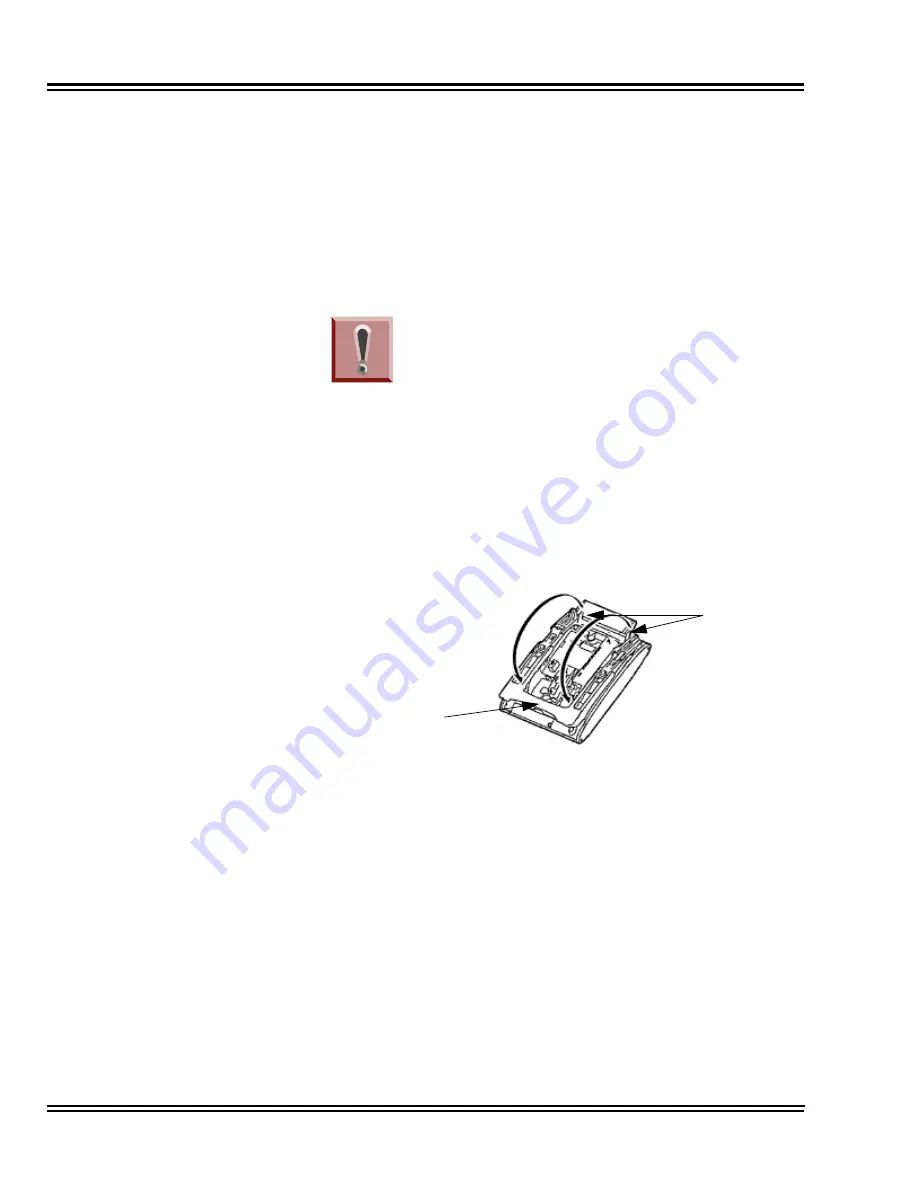
4.
Push the two stopper tabs through the slots to separate the tilt
leg from the leg support.
5.
Lay the tilt leg and the leg support flat to expose APR-L UNIT
compartment.
6.
Carefully pry loose the knockout covering the bottom option
interface (refer to
Figure 6-31 Bottom Option Interface
Knockout on page 6-41
).
Figure 6-30 Separate Tilt Leg from Leg Support
To prevent possible damage to the APR-L
UNIT or the DTL multiline terminal during
installation or removal, disconnect the line
cord and the AC/DC adapter from the DTL
multiline terminal.
Stoppers
Tilt Leg
Summary of Contents for Univerge SV9100
Page 1: ...System Hardware Manual Issue 1 2 January 2015...
Page 2: ...THIS PAGE INTENTIONALLY LEFT BLANK...
Page 40: ...Issue 1 2 UNIVERGE SV9100 1 16 Introduction to SV9100...
Page 105: ...UNIVERGE SV9100 Issue 1 2 System Hardware Manual 3 33 Figure 3 42 Brackets Small Batt Box...
Page 154: ...Issue 1 2 UNIVERGE SV9100 3 82 Installing the SV9100 Chassis...
Page 239: ...UNIVERGE SV9100 Issue 1 2 System Hardware Manual 4 85 Figure 4 24 Control Signal Connection...
Page 259: ...UNIVERGE SV9100 Issue 1 2 System Hardware Manual 4 105 NOTES...
Page 260: ...Issue 1 2 UNIVERGE SV9100 4 106 Installing the SV9100 Blades...
Page 412: ...Issue 1 2 UNIVERGE SV9100 5 152 Installing DT Series Digital and IP Multiline Terminals...
Page 476: ...Issue 1 2 UNIVERGE SV9100 6 64 Installing SV9100 Optional Equipment...


