


Lenze · 8400 HighLine · Reference manual · DMS 12.0 EN · 06/2017 · TD23
1348
17
Function library
17.1
Function blocks | L_DFRFG_1
_ _ _ _ _ _ _ _ _ _ _ _ _ _ _ _ _ _ _ _ _ _ _ _ _ _ _ _ _ _ _ _ _ _ _ _ _ _ _ _ _ _ _ _ _ _ _ _ _ _ _ _ _ _ _ _ _ _ _ _ _ _ _ _
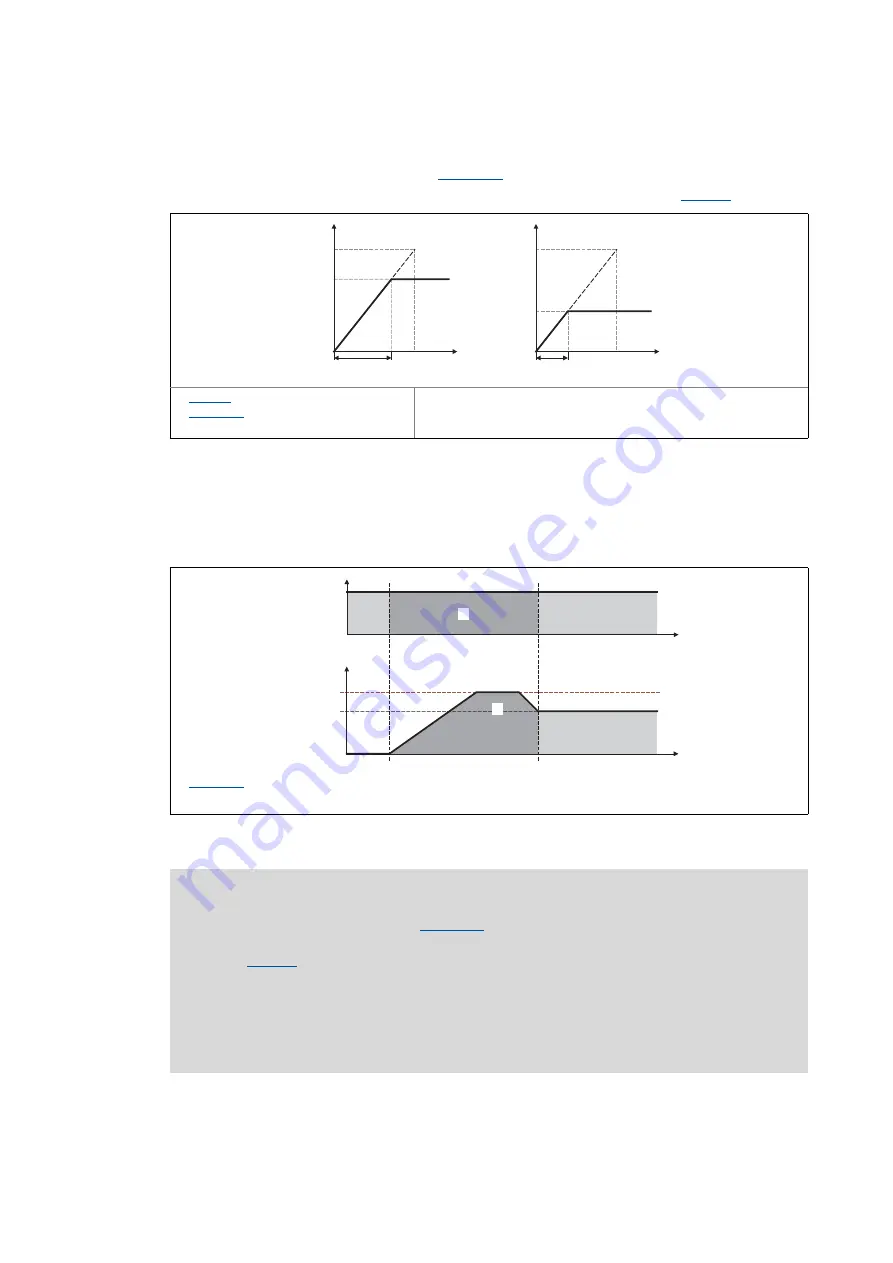
• The acceleration or deceleration in the synchronous point results from the
acceleration/deceleration time set in
• Reference for the acceleration/deceleration time is the reference speed (
[17-27] Connection between acceleration time and acceleration
• Based on the input speed of the master axis, a setpoint angle is calculated from the starting
time onwards which leads the actual angle of the slave.
• Dependent on the master speed and the settings for acceleration and offset, the FB may travel
oversynchronously for reducing the angular difference, i.e.
nOut_v
is higher than
nIn_v
:
[17-28] Speed/time diagram
: Reference speed
: Acceleration/deceleration
time
Effective target speed
Required time
v
t
0
1
v
t
0
1
: Maximum speed
Identical surface below the speed profile that represents the covered path.
nOut_v
nIn_v
t
nIn_v
t
0
0
Note!
• Set the maximum speed in
higher than the master speed to be expected.
The speed is selected on the motor side and is independent of the reference speed
(
). The higher the difference between maximum speed and master speed, the
less time to the synchronous time is required.
• In case of a heavily oscillating input speed it may occur that directly after setting the
bSync
status signal to TRUE the FB still executes slight angle corrections.
• Generally avoid acceleration or deceleration processes of the master axis while the
slave axes are synchronising.